

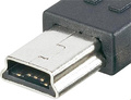
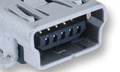
The Mini-A and Mini-B USB Connectors were released in April 2000 with USB 2.0 standard. Nowdays these connectors are obsolete and rarely used. They are superseeded by the Micro-USB connector and it's successor USB type-C.
| Pin | Name | Cable color | Description |
|---|---|---|---|
| 1 | VCC | Red | +5 VDC |
| 2 | D- | White | Data - |
| 3 | D+ | Green | Data + |
| 4 | ID | May be N/C, GND or used as an attached device presence indicator (tied to GND with resistor) | |
| 5 | GND | Black |
Ground |
USB pinout signals
USB is a serial bus (usb pinout and signals wiring diagram). It uses 4 shielded wires: two for power (+5v & GND) and two for differential data signals (labelled as D+ and D- in pinout). NRZI (Non Return to Zero Invert) encoding scheme used to send data with a sync field to synchronise the host and receiver clocks. In USB data cable Data+ and Data- signals are transmitted on a twisted pair. No termination needed. Half-duplex differential signaling helps to combat the effects of electromagnetic noise on longer lines. Contrary to popular belief, D+ and D- operate together; they are not separate simplex connections.
USB cable wires:
Shielded:
Data: 28 AWG twisted
Power: 28 AWG - 20 AWG non-twisted
Non-shielded:
Data: 28 AWG non-twisted
Power: 28 AWG - 20 AWG non-twisted
| Power Gauge | Max length |
|---|---|
| 28 | 0.81 m |
| 26 | 1.31 m |
| 24 | 2.08 m |
| 22 | 3.33 m |
| 20 | 5.00 m |

 correct
 incorrect