Hardware pinouts information and cables schemes

Welch Allyn Scanteam 8300-4 pinout

connector wiring scheme

bookmark this page
15 pin D-SUB female connector layout
15 pin D-SUB female connector
at the back of the 8300-4

for Scanteam 8300-4 check/MSR/barcode reader. Differs from 8300-1, 8300-2.

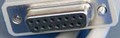
back of the 8300-4
Pin
Name Direction Description
1 Logic Ground  
2 VCC (+5vdc) For supplying +5 VDC to the scanner
3 RXD Receive data (RS-232 voltages)
4 CTS Clear to Send (RS-232 voltages)
5 KbdDataIn Keyboard wedge data (from a keyboard)
6 KbdClkIn Keyboard wedge clock (from a keyboard)
7 RDATA -?- OCIA
8 Data ready -?- OCR, or 5B RX/TX
9 Vin(+12vdc) +12 VDC input, optional if +5 VDC is supplied
10 Bootstrap Short to ground to enable bootstrap mode
11 TXD Transmit data (RS-232 voltages)
12 RTS Request to Send (RS-232 voltages)
13 KbdDataOut Keyboard data (to computer)
14 KbdClkOut Keyboard clock (to computer)
15 5B RX2/TX2 -?- 5B RX/TX (inverted)

This information should be correct, but may be not. Please, help us to improve this document!
Is this document CORRECT or INCORRECT? Your opinion will be used to establish document status (showed at the bottom).

Want to add or correct something here? Edit this page!
Pinouts.ru > Some peripheral devices pinouts > Pinout of Welch Allyn Scanteam 8300-4 and layout of 15 pin D-SUB female connector
Is it correct?:
unknown
Source(s) of this and additional information: Michael Graff
no reports
Last updated 2008-06-28 21:56:54. Edit this page. Is this document correct or incorrect? What is your opinion?
[Discuss at the forum] [Back to index] [SUBMIT new pinout]
This page contain parts under Copyright © 2000-2008 by pinouts.ru team.
No any portion of this webpage may be reproduced in any form without visible direct link to this page provided. Webmaster permission required in any other cases.
Efforts have been made to ensure this page is correct, but it is the responsibility of the user to verify the data is correct for their application.
8410 hits since April 17, 2006