| Device 1 Pin Number |
Device 1 Pin Name |
Direction | Device 2 Pin Number |
Device 2 Pin Name |
Description (may be empty) |
| 2 | RD | Receive | 4 | Serial Output | Serial Data from Alarm Panel - Red wire |
| 3 | TD | Transmit | 1 | Serial Input | Serial Data to Alarm Panel - Yellow Wire |
| 4 | DTR | Transmit | NC | Jumper to DSR | |
| 5 | SG | Ground | 2 | Ground | Signal Ground - Black |
| 5 | SG | Ground | 3 | Ground | Signal Ground - Black |
| 6 | DSR | Receive | NC | Jumper to DTR | |
The Pin red and yellow may be inverted, the pin number 1 is the red and in the table Device 2 is set as 4, the Mini-Molex has the pin 1 in the red wire location?
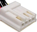
Connect the Molex to the PC-Link connector on the alarm panels main board. Connect it so that the red wire is directly beside the 'SO' printed on the circuit board.
You will also need the DSC software. This will not work with just a ordinary comm. program
Wire colors at the header are immaterial since the PC-LINK is sold as a small circuit board with a female header, and any other implementation could use arbitrary colors. It is possible to connect the header wrong, which causes the SI and SO connections to be swapped. A silk-screened bar appears on the alarm board to suggest how to orient the header (so the header board is next to the silk-screened bar. Pin 1 of the header is the SI connection, pin 4 is the SO connection. SI and SO appear on some alarm boards next to the header, but not all boards have that.


 правильная
 с ошибками