
| Pin |
Pin Name |
Description |
| 1 | DATA | Brown wire = Pin 1 on control board |
| 2 | CMD | Orange wire = Pin 2 on control board |
| 3 | 9VDC | White wire = Pin 4 on control board |
| 4 | GND | Purple + Black wire: Purple = Pin 8 on control board. Black = pin 3 on control board |
| 5 | VCC | Red Wire = pin 5 on control board |
| 6 | ATT | Yellow wire = pin 6 on control board |
| 7 | CLK | Blue wire = pin 7 on control board |
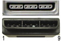
| 8 | N/C | Not connected (not used in PSX or PS2 controls and often not present in plug). Used for Light Gun games. |
| 9 | ACK | Green Wire = pin 9 on control board |
This applies to the Mad Catz. Dual force 2, programmable controller for PSX, PSONE, and PS2. The control board pins are numbered, but if unable to see due to the resin, pin one has a square PCB pad. If looking at the control from underside, with the lower casing removed, the pins can be counted sequentially from left to right. There should be 9 in total. PLEASE NOTE: both purple and black wires are connected to the same pin (pin 4) If the black wire is not connected, the vibrate function will operate continuously.
Hi , the scheme it's very useful and mainly correct , but i switched the position of purple wire with grey\white wire , and the joypad worked !
 правильная
 с ошибками