

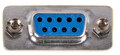
| Pin | Signal | Description |
| 1 | Up | |
| 2 | Down | |
| 3 | Left | |
| 4 | Right | |
| 5 | N/C | |
| 6 | Button 1 | |
| 7 | Light sensor (Light Phaser only) | |
| 8 | GND | |
| 9 | Button 2 |
Each button (left, right, button 1 ect.) is in fact a voltage(very small), this voltage is grounded to result in movement, fire, jump ect. For standard master system controllers this is directly feed to the system via wires only (some other controllers use a micro chip) they also are not connected to voltage, while some others do.
The Sega Genesis (in Europe sold as Sega MegaDrive) pads are an extension to the Sega Master System pads. They use more buttons (3+1, 5+1, 6+1). They use the one usnused pin as a select pin for reading more buttons.
Every single pin except for ground is connected to a power source. When the button or direction is pressed, a circuit is completed, and the current is drawn to the ground. This causes a drop in voltage which is read as a 0, low, or false on the system end. Inverse digital logic is used to make this low signal produce an action associated with the button.
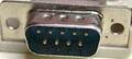
I wired up a 9 pin d-sub and hooked one up to my Raspberry Pi. The Genesis does have a power pin because there is an on board chip that controls a switch for determining the pin value. some pins are mutliplexed.
However, there are no on board chips which require a power source on the SMS controller. Hence, there is no power pin.

 correct
 incorrect