
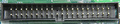
Advanced Technology Attachment (ATA), is a standard interface for connecting storage devices such as hard disks and CD-ROM drives inside personal computers. Nowdays superseeded by SATA (see SATA pinout).
ATA standards allow cable lengths in the range of 450 to 900 mm, so the technology normally appears as an internal computer storage interface. It provides the most common and the least expensive interface for this application.
| Pin | Name | Dir | Description |
|---|---|---|---|
| 1 | /RESET |  |
Reset |
| 2 | GND | Ground | |
| 3 | DD7 |  |
Data 7 |
| 4 | DD8 | |
Data 8 |
| 5 | DD6 | |
Data 6 |
| 6 | DD9 | |
Data 9 |
| 7 | DD5 | |
Data 5 |
| 8 | DD10 | |
Data 10 |
| 9 | DD4 | |
Data 4 |
| 10 | DD11 | |
Data 11 |
| 11 | DD3 | |
Data 3 |
| 12 | DD12 | |
Data 12 |
| 13 | DD2 | |
Data 2 |
| 14 | DD13 | |
Data 13 |
| 15 | DD1 | |
Data 1 |
| 16 | DD14 | |
Data 14 |
| 17 | DD0 | |
Data 0 |
| 18 | DD15 | |
Data 15 |
| 19 | GND | Ground | |
| 20 | KEY | - | Key (Pin missing) |
| 21 | DMARQ | ? | DMA Request |
| 22 | GND | Ground | |
| 23 | /DIOW | |
Write Strobe |
| 24 | GND | Ground | |
| 25 | /DIOR | |
Read Strobe |
| 26 | GND | Ground | |
| 27 | IORDY |  |
I/O Ready |
| 28 | SPSYNC:CSEL | ? | Spindle Sync or Cable Select |
| 29 | /DMACK | ? | DMA Acknowledge |
| 30 | GND | Ground | |
| 31 | INTRQ | |
Interrupt Request |
| 32 | /IOCS16 | ? | IO ChipSelect 16 |
| 33 | DA1 | |
Address 1 |
| 34 | PDIAG | ? | Passed Diagnostics. Used for 80-pin cable detect. |
| 35 | DA0 | |
Address 0 |
| 36 | DA2 | |
Address 2 |
| 37 | /IDE_CS0 | |
(1F0-1F7) |
| 38 | /IDE_CS1 | |
(3F6-3F7) |
| 39 | /ACTIVE | |
Led driver |
| 40 | GND | Ground |
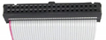
ATA/IDE cable
The IDE interface requires only one cable. All pins straight from 1 to 1, 2 to 2 and so on. The drives can be connected in any order. Only remember that one should be jumpered as Master and the other as Slave. If only one drive is used, jumper it as Single (if such a mode exists, or most common Master else).
Controller         Drive 1 or 2   Drive 1 or 2
+--+                   +--+            +--+
|::|===================|::|============|::|  <-Pin 1
|::|===================|::|============|::|
|::|===================|::|============|::|
|::|===================|::|============|::|
|::|===================|::|============|::|
|::|===================|::|============|::|
|::|===================|::|============|::|
+--+                   +--+            +--+
| Controller | Drive 1 | Drive 2 | |
|---|---|---|---|
| Wire 1-40 | 1-40 | 1-40 | 1-40 |
Each cable has two or three connectors, one of which plugs into a controller that interfaces with the rest of the computer system. The remaining one or two connectors plug into drives. Parallel ATA cables transfer data 16 or 32 bits at a time. One occasionally finds cables that allow for the connection of three ATA devices onto one IDE channel, but in this case one drive remains read-only (this type of configuration virtually never occurs).
For most of ATA's history, ribbon cables had 40 wires, but an 80-wire version appeared with the introduction of the Ultra DMA/66 standard. The 80-wire cable provides one ground wire to each signal wire. This reduces the effects of electromagnetic induction between neighboring wires and enables the 66 megabyte per second (MB/s) transfer rate of UDMA4. The faster UDMA5 and UDMA6 standards require 80-conductor cables. This was done to reduce crosstalk. Though the number of wires doubled, the number of connector pins remains the same as on 40-conductor cables. The connectors used for 80-way high speed ATA cables are not the same as the 40-pin connectors. Externally they look the same, but internally they are much more complicated, with a grounding rail along the body to earth all the extra shielding wires in the cable.
PATA Slave/Master configuration
If two drives attach to a single cable, the configuration generally sees one as a master and the other as a slave. The master drive generally shows up ahead of the slave drive when the computers operating system enumerates available drives. The master drive arbitrates access to devices on the channel. Because of this, latency-sensitive devices such as early CD-RW drives often benefitted from functioning as a master, and each channel must have a master in order to function properly.
In a drive setting called cable select the drives automatically configure themselves as master or slave. This is achieved by cutting wire 28 (on 40 wire cables, or wires 56 and 57 on 80 wire cables) between the two HDD/CDROM connectors. Some newer cables have this done internally in the connectors. In this case, the two connectors are of different colours.
 правильная
 с ошибками