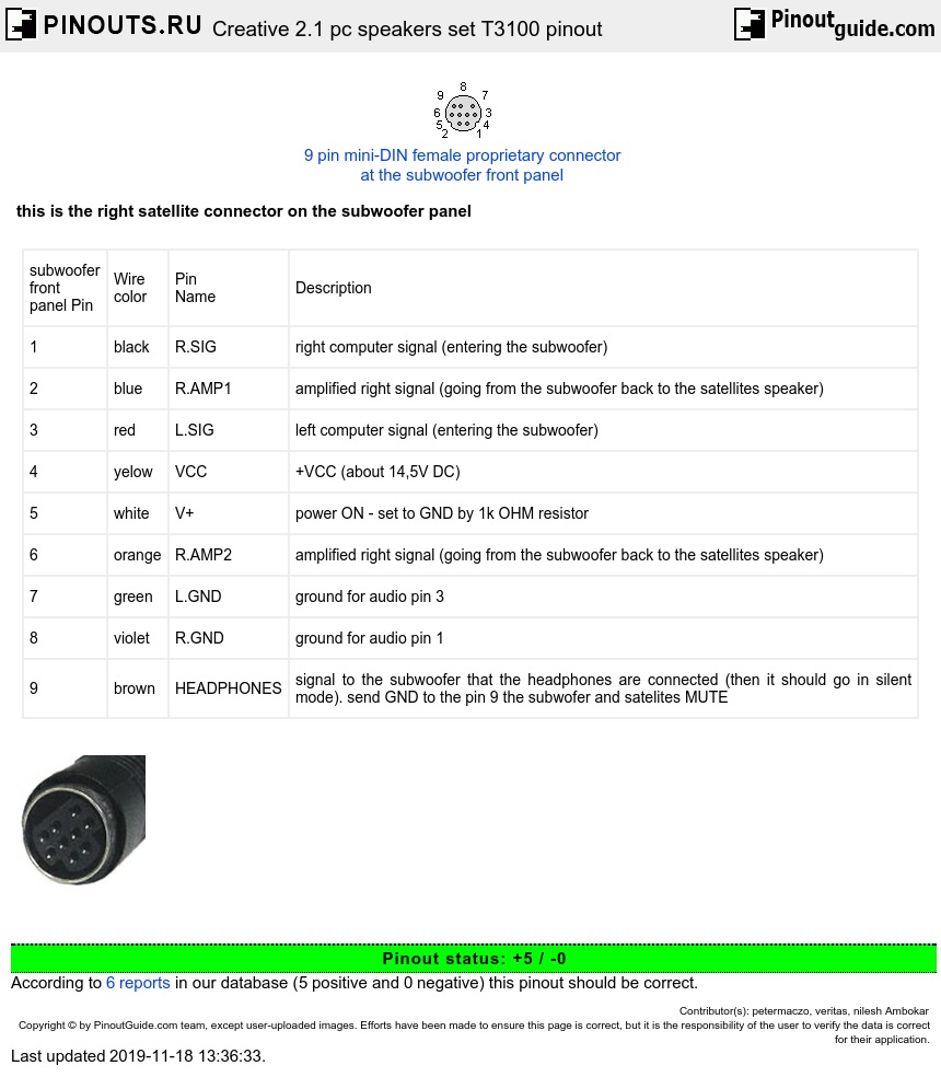
| subwoofer front panel Pin |
Wire color |
Pin Name |
Description |
| 1 | black | R.SIG | right computer signal (entering the subwoofer) |
| 2 | blue | R.AMP1 | amplified right signal (going from the subwoofer back to the satellites speaker) |
| 3 | red | L.SIG | left computer signal (entering the subwoofer) |
| 4 | yelow | VCC | +VCC (about 14,5V DC) |
| 5 | white | V+ | power ON - set to GND by 1k OHM resistor |
| 6 | orange | R.AMP2 | amplified right signal (going from the subwoofer back to the satellites speaker) |
| 7 | green | L.GND | ground for audio pin 3 |
| 8 | violet | R.GND | ground for audio pin 1 |
| 9 | brown | HEADPHONES | signal to the subwoofer that the headphones are connected (then it should go in silent mode). send GND to the pin 9 the subwofer and satelites MUTE |
shield must be connected to GND
 correct
 incorrect