The Front right speaker controls the inputs and outputs of the system. There are 3 inputs to this speaker to make the whole system work:
Green: Front Speakers
Black: Rear Speakers
Orange:Subwoofer and Center
These are the sound inputs and they pass through a small circuit in the Front Right speaker when they then go to the Subwoofer to be amplified and distributed.
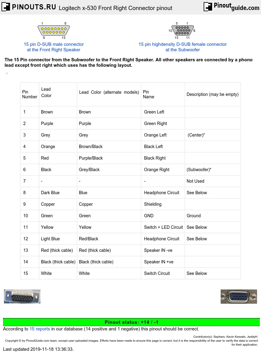
The Front Right Speaker also controls the output, by means of the potentiometer, switch and headphone sockets, the functions of the circuit are at the bottom and the pinout for the 15pin HD D-connector is below. The numbers are different from common 15pin HD D-connectors but they follow the pinout diagram.
| Pin Number |
Lead |
Lead Color (alternate models) |
Pin Name |
Description (may be empty) |
| 1 | Brown | Brown | Green Left | |
| 2 | Purple | Purple | Green Right | |
| 3 | Grey | Grey | Orange Left | (Center)* |
| 4 | Orange | Brown/Black | Black Left | |
| 5 | Red | Purple/Black | Black Right | |
| 6 | Black | Grey/Black | Orange Right | (Subwoofer)* |
| 7 | - | - | - | Not Used |
| 8 | Dark Blue | Blue | Headphone Circuit | See Below |
| 9 | Copper | Copper | Shielding | |
| 10 | Green | Green | GND | Ground |
| 11 | Yellow | Yellow | Switch + LED Circuit | See Below |
| 12 | Light Blue | Red/Black | Headphone Circuit | See Below |
| 13 | Red (thick cable) | Red (thick cable) | Speaker IN -ve | |
| 14 | Black (thick cable) | Black (thick cable) | Speaker IN +ve | |
| 15 | White | White | Switch Circuit | See Below |
*I think this is correct however I may be wrong,
Switch Layout
The Switch is a DPDT switch:
TO LED
ON
| O | O | PIN 11 | ||
| 6V | O | IN | O | PIN 15 |
| Unused | O | OFF | O | Unused |
Potentiometer Layout
The Potentiometer has 6 Input and Outputs for each channel, providing between 10K and 0K resistance.
Each pin has this Layout:
+ OUT -
O-----O-----O
\/
|-[ 10K ]-|
O
O
| O | O | Orange Right (Sub)* | |
| O | O | O | Black Right |
| O | O | O | Black Left |
| O | O | Orange Left (Center)* | |
| O | O | O | Green Right |
| O | O | O | Green Left |
Headphone Circuit
The headphone socket contains two pins that break the circuit if anything is plugged in.
This determines whether or not to allow the speakers and amplifier to work in the Subwoofer.
This is the circuit:
Pin 8 Switch Headphone Socket Pin 12
O-----------O/ O---------------O _|_ O-----------O
If there is not a direct connection between 8 and 12 sound will only come out of the headphone socket.
LED Circuit
6V comes out of the switch and into the power LED, this then has a few resistors but ends up at pin 11. Im guessing pin 11 is some sort of Ground or leads onto another circuit inside the Subwoofer, therefore can't really so much with pin 11.
Switch Circuit
There is 6V coming into the speaker and this passes through the main DPDT Switch. When the switch is closed the 6V isn't taken anywhere significant or obvious as far as I could tell. But when it is on it goes to the Power LED and then on to more things that I haven't looked at. The other side of the DPDT links pin 15 and 11 together which must form another circuit inside the Subwoofer activating the amplifier and speakers.
Therefore as with the headphone socket there needs to be a direct connection between pin 15 and 11 to make the speaker work.
*I think this is correct however I may be wrong,
Just using the sub
I did some tinkering with this speaker system, my intention was to just use the sub woofer part because my monitors for my M-box lacking in bass response.
This works fine for me, I also made a 2 1/4 mono inputs to combined mono RCA for this project, so I have a summed input for the sub.

td


 correct
 incorrect