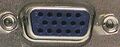
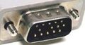
Hardware pinouts information and cables schemes

Atari Enhanced joystick pinout

connector or cable wiring scheme

bookmark this page

Can be found at Atari Falcon, Jaguar & STe.

Pin Name Description
1UP0Up 0
2DOWN0Down 0
3LEFT0Left 0
4RIGHT0Right 0
5PAD0YPaddle 0 Y
6FIRE0/LIGHT GUNFire 0/Lightgun
7VCC+5 VDC
8n/cNot connected
9GNDGround
10FIRE2Fire 2
11UP2Up 2
12DOWN2Down 2
13LEFT2Left 2
14RIGHT2Right 2
15PAD0XPaddle 0 X

This information should be correct, but may be not. Please, help us to improve this document!
Is this document CORRECT or INCORRECT? Your opinion will be used to establish document status (showed at the bottom).

Want to add or correct something here? Edit this page!
Pinouts.ru > Input devices (keyboards, mices, joysticks) pinouts > Pinout of Atari Enhanced joystick and layout of 15 pin highdensity D-SUB female connector and 15 pin highdensity D-SUB male connector
Is it correct?:
unknown
Source(s) of this and additional information: Do-It-Yourself Atari Jaguar Controller by Andrew Hague, from Hardware Book
no reports
Last updated 2008-06-28 21:56:54. Edit this page. Is this document correct or incorrect? What is your opinion?
[Discuss at the forum] [Back to index] [SUBMIT new pinout]
This page contain parts under Copyright © 2000-2008 by pinouts.ru team.
No any portion of this webpage may be reproduced in any form without visible direct link to this page provided. Webmaster permission required in any other cases.
Efforts have been made to ensure this page is correct, but it is the responsibility of the user to verify the data is correct for their application.
13198 hits since March 4, 2005