

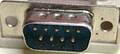
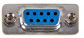
| Pin | Name | Dir | Description |
|---|---|---|---|
| 1 | /FORWARD | Forward | |
| 2 | /BACK | Backward | |
| 3 | /LEFT | Left | |
| 4 | /RIGHT | Right | |
| 5 | +5V | +5 VDC (50mA max) | |
| 6 | /TRG1 | Trigger A / Output 1 | |
| 7 | /TRG2 | Trigger A / Output 1 | |
| 8 | OUTPUT | Output 3 | |
| 9 | GND | Signal Ground |

 correct
 incorrect
If you did publish instruction for Do-It-Yourself device with this pinout, share the link with us.