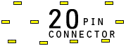
2..................20
1..................19
Viewed from the top (connector) side of the motherboard.
| Motherboard Pin Name |
Motherboard Pin Number |
Direction | Pin Number |
Pin Name |
Description |
| Data0- | 1 | -?- | Data - for USB port 0 (Bottom) | ||
| Data0+ | 3 | -?- | Data + for USB port 0 (Bottom) | ||
| Data1- | 5 | -?- | Data - for USB port 1 (top) | ||
| Data1+ | 7 | -?- | Data + for USB port 1 (top) | ||
| GND | 9 | -?- | Ground | ||
| GND | 11 | -?- | Ground | ||
| Left Audio In * | 13 | -?- | Input for rear Audio (L) * | ||
| Right Audio In * | 15 | -?- | Input for rear Audio (R) * | ||
| GND | 17 | -?- | Ground | ||
| MIC IN | 19 | -?- | Microphone Input (+) | ||
| Detect ** | 2 | -?- | See below ** | ||
| Vcc | 4 | -?- | +5V for USB ~Both~ | ||
| ? | 8 (may be 6?) | -?- | Unknown | ||
| Vcc | 6 (may be 8?) | -?- | +5V for USB ~Both~ | ||
| Ring * | 10 | -?- | Speaker Ring & RS Terminal * | ||
| Tip * | 12 | -?- | Speaker Tip & TS Terminal * | ||
| Detect ** | 14 | -?- | See below ** | ||
| Keyed | 16 | -?- | No pin | ||
| GND | 18 | -?- | Ground | ||
| ? | 20 | -?- | Unknown |
To use this board in a non-dell case w/o front USB & sound:
* Jump (connect) pins 10-13 (L) and 12-15 (R) for rear sound.
** Jump (connect) pins 2-14 to avoid Front panel USB cable not detected error.
The Dell Dimension 2400 uses the standard 9 pin USB header for the front ports and use a separate connector for the front headphone jack (the same connector used on many dells of that era).
 correct
 incorrect