On the old mainboards (Pentium III) 8-pin IDC male connector is used with pins for 2-nd USB port in reversed order. Sometimes more exotical layouts were used.
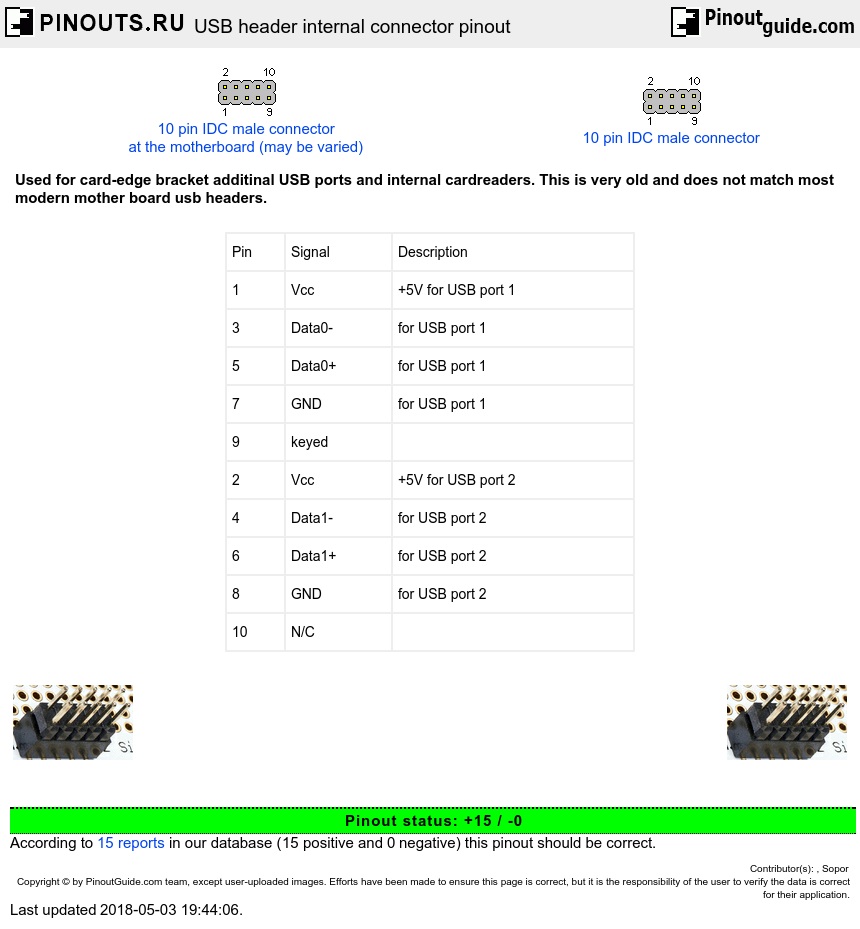
| Pin | Signal | Description |
| 1 | Vcc | +5V for USB port 1 |
| 3 | Data0- | for USB port 1 |
| 5 | Data0+ | for USB port 1 |
| 7 | GND | for USB port 1 |
| 9 | keyed | |
| 2 | Vcc | +5V for USB port 2 |
| 4 | Data1- | for USB port 2 |
| 6 | Data1+ | for USB port 2 |
| 8 | GND | for USB port 2 |
| 10 | N/C |
This is a sample pinout from Epox motherboard manual. It may be DIFFERENT for other motherboards.
In various MB USB pin for 2nd port is reversed. V+ swap with GND and D- with D+ ! Detect direction by power pins before connect.
Before connecting any external bracket you should check them and replug wires according to your motherboard manual USB pinout (if needed).
If you have no access to the motheboard manual, you can try determine pinout manually by finding GND and +5V manually with multimeter.
USE AT YOU OWN RISK! May be dangerous for your equipment!
WARNING! !!!
Old motherboard one series in the connector can be deployed in the opposite direction!!!
 correct
 incorrect