
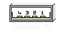
| Pin | Signal | Description |
| 1,2,3,4 | Charger In, +5.4 V | May be connected to USB pin 1 VCC in USB data cable |
| 5,6 | +1.6 V | Acc. Det. ? |
| 8 | GND | May be used as Serial CTS? |
| 9 | RTS? | |
| 10 | Rx | Serial IN (TTL) |
| 11 | Tx | Serial OUT (TTL) |
| 12 | GND | Serial GND |
| 13 | DSR? | |
| 14 | DTR? | |
| 15,16,17 | GND | connect to USB pin 4 in USB cable |
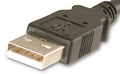
| 21 | USB +5V in | connect to USB pin 1 Vcc in USB cable |
| 22 | USB D+ | connect to USB pin 3 in USB cable |
| 23 | USB D- | connect to USB pin 2 in USB cable |
| 25 | 5V TTL out | |
| 26 | 5V ID-BIT 0 | to VGA connector pin 12 (used to build your own VGA cable) |
| 27 | 5V TTL out | |
| 28 | H-SYNC | to VGA pin 13 |
| 29 | V-SYNC | to VGA pin 14 |
| 30 | SYNC GND | to VGA pin 10 |
| 31 | BLUE signal | to VGA pin 3 |
| 32 | BLUE GND | to VGA pin 8 |
| 33 | RED signal | to VGA pin 1 |
| 34 | RED GND | to VGA pin 6 |
| 35 | GREEN signal | to VGA pin 2 |
| 36 | GREEN GND | to VGA pin 7 |
Pins 25-36 are VGA OUT (mirror mode only). Pins 8-14 are TTL SERIAL I/O.

 correct
 incorrect