
ECP use protocol with additional hardware to generate hand shaking signals (like EPP) and runs at very much the same speed than the EPP mode, but usually works better due to use of DMA channels and FIFO buffer for the sending and/or receiving of data. Another feature of ECP is a real time data compression. It uses Run Length Encoding (RLE) to achieve data compression ratios up to 64:1. This comes is useful with devices such as Scanners and Printers where a good part of the data is long strings which are repetitive.
ECP as with EPP is backwards compatible with old style printers and devices, but when advance devices are connected the ECP port can transfer data at higher speeds and with more versatility. By including a complete protocol, every transfer is negotiated by asking the connected device its capabilities. This means that when using a printer with ECP capabilities and using compression, the port will automatically transfer the data in the best and fastest possible way.
By using a simple compression called RLE (Run Length Encoding), the ECP port can boost the speed of transmitting data. The RLE scheme is a simple byte level data compression system that will effectively compress long sequences of the same byte by using a two byte code that is transmitted by sending the repeated byte and the number of times it is repeated in the sequence. This method works over repeated byte strings of up to 128 bytes, which means that it allows a maximum compression of 64:1. This method is good for images that often contain long streams of the same bytes, but in regular text output, this method is not very effective.
The ECP port is also designed to accept multiple devices on a single port. To accomplish this task, it uses its own addressing scheme, it sends a channel address command on the parallel port bus (data lines). By doing this the port tells all devices, except the one to witch the stream of data is meant for, to ignore all forthcoming data, until the next channel address command. If no channel address command is sent for a given transfer, it defaults to the address zero. This addressing scheme gives it the possibility to connect up to 128 different devices or channel addresses and used in some combo devices (i.e. printer+scanner+fax). Howether this was never used.
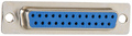
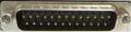
While Extended Capabilities Printer Ports use exactly the same D25 connector as your SPP, ECP assigns different tasks to each of the pins, just like EPP. This means that there is also a different handshake method when using a ECP interface.
While Extended Capabilities Printer Ports use exactly the same 25 pin D-SUB connector as SPP, ECP assigns different tasks to each of the pins, just like EPP. This means that there is also a different handshake method when using a ECP interface. The ECP is backwards compatible to the SPP and EPP. When operating in SPP mode, the individual lines operate in exactly the same fashion than the SPP (use SPP LPT port pinout). In ECP mode pinout is following:
| Pin | Name | Dir | Description |
|---|---|---|---|
| 1 | HostCLK |  |
Strobe; A low on this line indicates, that there is valid data at the host. When this pin is de-asserted, the +ve clock edge should be used to shift the data into the device. |
| 2 | data0 |  |
Address, Data or RLE Data Bit 0 |
| 3 | data1 | |
Address, Data or RLE Data Bit 1 |
| 4 | data2 | |
Address, Data or RLE Data Bit 2 |
| 5 | data3 | |
Address, Data or RLE Data Bit 3 |
| 6 | data4 | |
Address, Data or RLE Data Bit 4 |
| 7 | data5 | |
Address, Data or RLE Data Bit 5 |
| 8 | data6 | |
Address, Data or RLE Data Bit 6 |
| 9 | data7 | |
Address, Data or RLE Data Bit 7 |
| 10 | PeriphCLK |  |
Acknowledge, A low on this line indicates, that there is valid data at the Device. When this pin is deasserted, the +ve clock edge should be used to shift the data into the Host. |
| 11 | PeriphAck | |
When in reverse direction a HIGH indicates Data, while a LOW indicates a Command Cycle. In forward direction, functions as PeriphAck. |
| 12 | nAckReverse | |
When Low, Device acknowledges Reverse Request. |
| 13 | X-Flag | |
Extensibility Flag |
| 14 | Host Ack | |
When in forward direction a HIGH indicates Data, while a LOW indicates a Command Cycle. In reverse direction, functions as HostAck. |
| 15 | PeriphRequest | |
A LOW set by the device indicates reverse data is available. |
| 16 | NReverse Request | |
A LOW indicates data is in reverse direction. |
| 17 | 1284 Active | |
A HIGH indicates Host is in 1284 Transfer Mode. Taken low to terminate. |
| 18 | GND | Signal Ground | |
| 19 | GND | Signal Ground | |
| 20 | GND | Signal Ground | |
| 21 | GND | Signal Ground | |
| 22 | GND | Signal Ground | |
| 23 | GND | Signal Ground | |
| 24 | GND | Signal Ground | |
| 25 | GND | Signal Ground |
This file is not intended to be a thorough coverage of the standard. It is for informational purposes only, and is intended to give designers and hobbyists sufficient information to design their own ECP compatible devices.
IEEE 1284 Signal Line Descriptions :
|
SPP Signal |
EPP Signal |
ECP Signal |
Source |
Pinout |
| Data8-1 Unidirectional data lines. Data8 is the most significant. |
AD8-1 Bi-directional address and data lines. AD8 is the most significant. |
Data8-1 Bi-directional address and data lines. Data8 is the most significant. |
Host/ Peripheral |
1284-A: 9 - 2 1284-B: 9 - 2 1284-C: 13 - 6 |
| STROBE* Data is valid during an active low pulse on this line. |
WRITE* This signal is low during a write operation and high during a read operation. |
HostClk This forward direction handshaking line is interlocked with PeriphAck and driven low when data is valid. |
Host | 1284-A: 1 1284-B: 1 1284-C: 15 |
| AUTOFD* Usage of this line varies. Most printers will perform a line feed after each carriage return when this line is low, and carriage returns only when this line is high. |
DSTROBE* This signal denotes data cycles. During a write operation, data is valid when this signal is active. During a read operation, this signal is low when the host is ready to receive data. |
HostAck In the forward direction, this line is driven low for a command transfer, and high for a data transfer. In the reverse direction, this signal is a handshaking line interlocked with PeriphClk. |
Host | 1284-A: 14 1284-B: 14 1284-C: 17 |
| INIT* This line is held low for a minimum of 50 µs to reset the printer and clear the print buffer. |
INIT* This line is driven low to terminate EPP mode and return to SPP mode. |
ReverseRequest* This line is driven low to place the parallel port interface in the reverse direction. |
Host | 1284-A: 16 1284-B: 31 1284-C: 14 |
| SelectIn* The host drives this line low to select the peripheral. |
ASTROBE* This line denotes address cycles. When this signal is low, AD8-1 is an address. |
1284 Active The host drives this line high while in ECP mode, and low to terminate ECP mode. |
Host | 1284-A: 17 1284-B: 36 1284-C: 16 |
| ACK* The peripheral pulses this line low when it has received the previous data and is ready to receive more data. The rising edge of ACK* can be enabled to interrupt the host. |
INTR* The peripheral can enable this signal to interrupt the host on the low to high transition. |
PeriphClk The peripheral drives this reverse direction handshaking line low to indicate that the data is valid. PeriphClk is interlocked with HostAck. |
Peripheral | 1284-A: 10 1284-B: 10 1284-C: 3 |
| BUSY The peripheral drives this signal high to indicate that it is not ready to receive data. |
WAIT* The peripheral drives this signal low to acknowledge that it has successfully completed the data or address transfer initiated by the host. |
PeriphAck This forward direction handshaking line is interlocked with HostClk and driven by the peripheral to acknowledge data received from the host. During reverse direction transfers, the peripheral drives this line high during data transfers and low during command transfers. |
Peripheral | 1284-A: 11 1284-B: 11 1284-C: 1 |
| PError Usage of this line varies. Printers typically drive this signal high during a paper empty condition. |
User Defined | AckReverse* The peripheral drives this line to follow the level of the ReverseRequest* line. |
Peripheral | 1284-A: 12 1284-B: 12 1284-C: 5 |
| Select The peripheral drives this signal high when it is selected and ready for data transfer. |
User Defined | XFlag The peripheral drives this line high to indicate that it uses ECP mode. |
Peripheral | 1284-A: 13 1284-B: 13 1284-C: 2 |
| FAULT* Usage of this line varies. Peripherals usually drive this line low when an error condition exists. |
User Defined | PeriphRequest* The peripheral drives this signal low to request a reverse transfer. This line can be used to interrupt the host. |
Peripheral | 1284-A: 15 1284-B: 32 1284-C: 4 |
The IEEE 1284 standard was approved in march 1994 as the Standard Signaling Method for a Bidirectional Parallel Peripheral Interface for Personal Computers. And is the first approved standard for parallel transmission on PCs. The idea was to create a standard that was backward compatible with the old Centronics standard. With the new standard higher speeds and greater distances are possible plus there is the capability also sending to the host (bidirectional).
The maximum speed that is allow over the new parallel bus is 2 MBps (16 Mbps). The cable length is determend by the mode that is used. Within the IEEE 1284 there are 5 different modes defined:
Parallel port Compatibility modes
This one is compatible with all previous version of the parallel port. Data rates are possible up to 150 bytes per second @ 6 meter (20 ft) with an AB-cable or up to 150 kbps @ 10 meter (32.8 ft) with a CC-cable.
Nibble mode
This is a uni-directional interface. Only data transfers from periperal to host are possible. Data is send from the e.g. printer to the PC in a nibbles (4 bits). Combined with the Compatibility mode this is what Hewlett Packard calls Bi-tronics.
For the Nibble-mode speeds of up to 50 kbps @ 6 meter (20 t) are possible. With a CC-cable this can be increased to up to 150 kbps @ 10 meter (32.6 ft).
Byte mode
Byte mode makes it possible to send data from the peripheral to the host in bytes (8 bits). Combined with the Compatibility mode you have a Bidirectional port.
Speeds are possible up to 500 kbps @ 10 meter (32.8 ft) when CC-cables are used.
EPP mode
This is a mode in which data can be transfered from host to peripheral or vice versa, but not at the same time, so this is a half-duplex connection (mostly used by CD-ROMs, tape-drives, harddisks).
Speeds can range from 500 kbps to up to 2 Mbps @ 6 meter (20 ft) or 10 meter (32.8 ft) when CC-cables are used.
ECP mode
This is a mode in which data can be transfered from host to peripheral or vice versa, but not at the same time, so this is a half-duplex connection (mostly used by printers and scanners).
Speeds can range from 500 kbps to up to 1 Mbps @ 6 meter (20 ft) or 10 meter (32.8 ft) when CC-cables are used.
Every device can only be in one mode at a time. So the IEEE 1284 workgroup invented a way of determining which mode should be used with which device, that is called Negotiation. The Negotiation part doesn't affect older devices, but IEEE 1284 compliant devices can tell the host what they are and which mode to use.
IEEE-1284 Cables and Connectors
The IEEE defined three types of connectors and six types of cables. The type A connector is the parallel port connector (Sub-D25) found on most computers. The type B connector is what is usually called the Centronics connector. And there is a connector that is called MDR36 and which is called type C. The pinning for the Centronics and Sub-D25 is not changed.
|
AMAM |
Type A male to type A male |
|
AMAF |
Type A male to type A female |
|
AB |
Type A male to type B |
|
AC |
Type A male to type C |
|
BC |
Type B male to type C |
|
CC |
Type C male to type C |
IEE-1284 cable characteristics are defined:
The cable shield must be connected to the connector back shell using a 3600 concentric method
The shield must be minimal 85 % optical braid coverage over foil
The maximum crosstalk is not greater then 10 %
All signals are send over a twisted pair with their signal ground return
Each pair must have an impedance of 62 +/- 6 ohms @ 4 to 16 MHz
 правильная
 с ошибками