
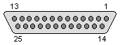
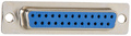
Parallel port allow the input of up to 9 bits or the output of 12 bits at any one given time. This port may be used for interfacing home made projects since external circuitry is minimal for many simple tasks. The port is composed of 4 control lines, 5 status lines and 8 data lines. Nowdays is obsolete and rarely found on the back of your PC (note, that 25 pin D-SUB male connector may represent RS-232 serial port, which is not compatible with LPT!).
There are differnt modes of Parallel port work in modern computer. Take a look to ECP Parallel LPT port (IEEE-1284A) interface for more detailed explanations. Information included in current page is about older SPP LPT port interface. ECP specification includes SPP as one of possible modes.
| Pin | Name | Dir | Description |
|---|---|---|---|
| 1 | /STROBE |  |
Strobe |
| 2 | D0 | |
Data Bit 0 |
| 3 | D1 | |
Data Bit 1 |
| 4 | D2 | |
Data Bit 2 |
| 5 | D3 | |
Data Bit 3 |
| 6 | D4 | |
Data Bit 4 |
| 7 | D5 | |
Data Bit 5 |
| 8 | D6 | |
Data Bit 6 |
| 9 | D7 | |
Data Bit 7 |
| 10 | /ACK |  |
Acknowledge |
| 11 | BUSY | |
Busy |
| 12 | PE | |
Paper End |
| 13 | SEL | |
Select |
| 14 | /AUTOFD | |
Autofeed |
| 15 | /ERROR | |
Error |
| 16 | /INIT | |
Initialize |
| 17 | /SELIN | |
Select In |
| 18 | GND | Signal Ground | |
| 19 | GND | Signal Ground | |
| 20 | GND | Signal Ground | |
| 21 | GND | Signal Ground | |
| 22 | GND | Signal Ground | |
| 23 | GND | Signal Ground | |
| 24 | GND | Signal Ground | |
| 25 | GND | Signal Ground |
The data output of the Parallel Port is normally TTL logic levels. Most Parallel Ports implemented in ASIC, can sink and source around 12mA. However, there are other variations possible: Sink/Source 6mA, Source 12mA/Sink 20mA, Sink 16mA/Source 4mA, Sink/Source 12mA and others.
Centronics is an early used standard for transferring data from a host to the printer. The majority of printers use this handshake.
               ______          ___________________
 nStrobe             \        /
                      \______/
                       ______________
 Busy                 /              \
               ______/                \___________
               ______________________         ____
 nAck                                \       /
                                      \_____/
               ___    _______    _________________
                     /         /
 Data               /         /
                   /         /
               __/  \_______/  \_________________
Data is first applied on the Parallel Port pins 2 to 7. The host then checks to see if the printer is busy. i.e. the busy line should be low. The program then asserts the strobe, waits a minimum of 1mS, and then de-asserts the strobe. Data is normally read by the printer/peripheral on the rising edge of the strobe. The printer will indicate that it is busy processing data via the Busy line. Once the printer has accepted data, it will acknowledge the byte by a negative pulse about 5mS on the nAck line. Host may ignore the nAck line to save time.
Note: Connecting as a SPP interface, it's important to initialize the printer putting on low the Init Pin, (16 for the IEEE-1284A interface) and also to ground the 'Select Printer' (17 on the same interface). Otherwise, no matter how much data you send, the printer will not understand anything!
 правильная
 с ошибками