| Port pin | Description |
|---|---|
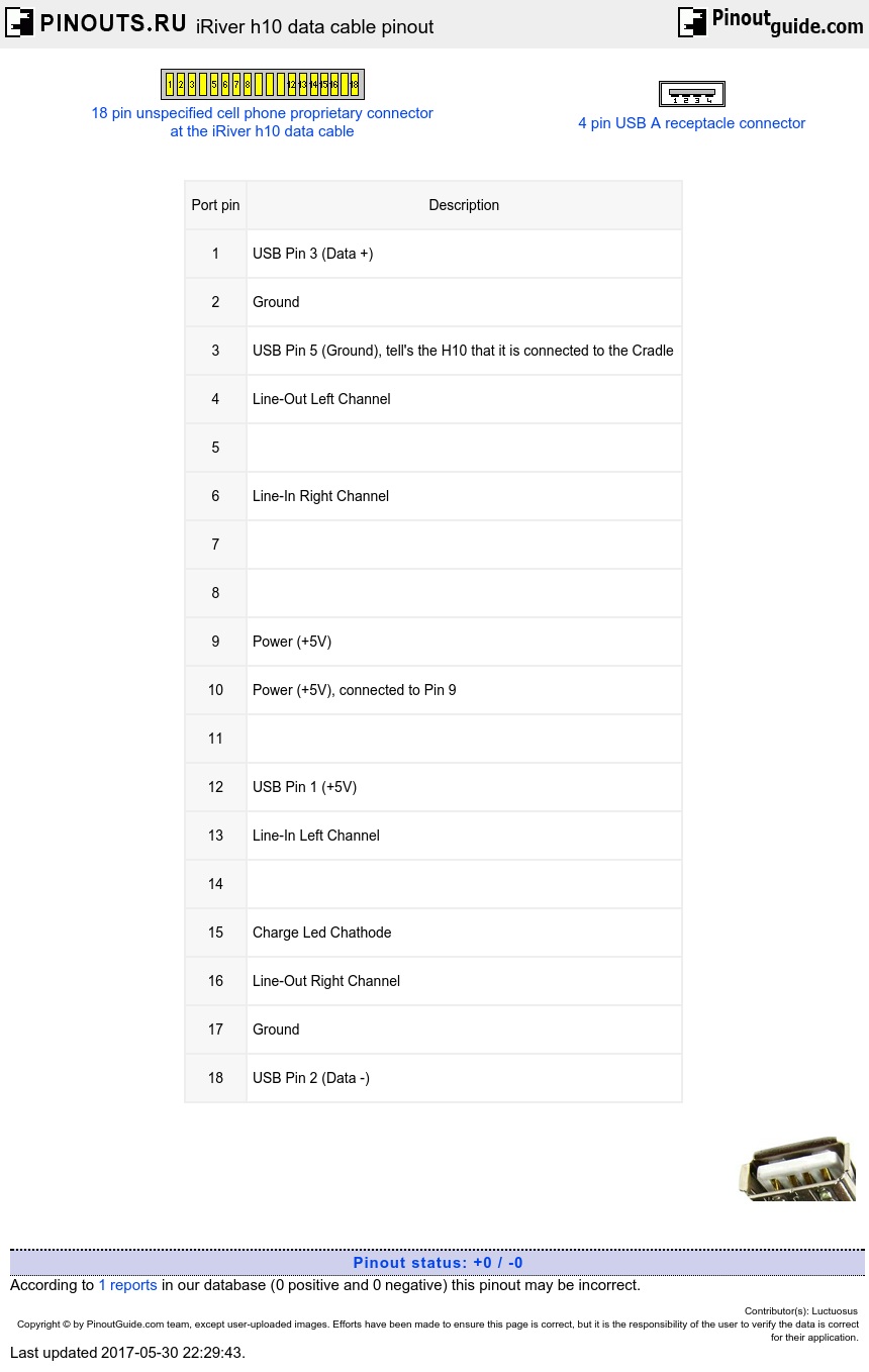
| 1 | USB Pin 3 (Data +) |
| 2 | Ground |
| 3 | USB Pin 5 (Ground), tell's the H10 that it is connected to the Cradle |
| 4 | Line-Out Left Channel |
| 5 | |
| 6 | Line-In Right Channel |
| 7 | |
| 8 | |
| 9 | Power (+5V) |
| 10 | Power (+5V), connected to Pin 9 |
| 11 | |
| 12 | USB Pin 1 (+5V) |
| 13 | Line-In Left Channel |
| 14 | |
| 15 | Charge Led Chathode |
| 16 | Line-Out Right Channel |
| 17 | Ground |
| 18 | USB Pin 2 (Data -) |
An alternative pinout suggested by our contributor
1) DP
2) DN
3) GND
4) GND
5) CRADLE_DET
6) LINEOUT_R
7) LINEOUT_L
8) /M_CHRG
9) /OC_OUT
10) HOST_PWR_EN
11) LINEIN_R
12) LINEIN_L
13) USB_ID
14) VBUS
15) VDD_5
16) VDD_5
17) ADP_5
18) ADP_5

 correct
 incorrect