

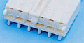
An AT power supply delivers +5 V, +12 V, -5 V and -12 V voltages using two six-pin connectors. A few newer boards used an aditional connector for +3.3 V. Note, that you must install these connectors to the motherboard in a way that the black wires are placed on the center, or your equipment will be damaged.
P8 AT power supply connector
| Pin | Name | Color | Description | |
|---|---|---|---|---|
| 1 | PG | Orange | Power Good, +5 VDC when all voltages have stabilized. | |
| 2 | +5V | Red | +5 VDC (or n/c) | |
| 3 | +12V | Yellow | +12 VDC | |
| 4 | -12V | Blue | -12 VDC | |
| 5 | GND | Black | Ground | |
| 6 | GND | Black | Ground |
P9 AT power supply connector
| Pin | Name | Color | Description | |
|---|---|---|---|---|
| 1 | GND | Black | Ground | |
| 2 | GND | Black | Ground | |
| 3 | -5V | White or Yellow | -5 VDC | |
| 4 | +5V | Red | +5 VDC | |
| 5 | +5V | Red | +5 VDC | |
| 6 | +5V | Red | +5 VDC |
P10 AT aux power supply connector (found on some Dell socket 5, 7 and 8 motherboards). The proprietary 3.3V connector is not only for Dell, but also IBM (especially Power Series) and Intel (e.g. Atlantis Socket 5 and similar Socket 7 mainboards). According to Intel documentation (e.g. Intel Advanced/AS mainboard), the pinout stays the same as shown in the document.
The 3.3V has been used exclusively to power PCI slots - while on-board internal regulator usually makes 3.3V for chipset and CPU, it may be too weak for some PCI boards so in early mainboards it is not routed to slots.
|
Pin |
Name | Color | Description | |
| 1 | GND | Black | Ground | |
| 2 | GND | Black | Ground | |
| 3 | GND | Black | Ground | |
| 4 | 3.3v | Green | +3.3 VDC | |
| 5 | 3.3v | Green | +3.3 VDC | |
| 6 | 3.3v | Green | +3.3 VDC |

 правильная
 с ошибками