RS-232 is simple, universal, well understood and supported. It was introduced in 1960, and despite rumors for its early demise, has remained used through the industry.
RS-232 key features
- Single-Ended
- Point-to-Point Interface
- Large Polar Driver Output Swing
- Controlled Driver Slew Rate
- Fully Defined Interface
- 20 kbps Maximum Data Rate
RS-232 details
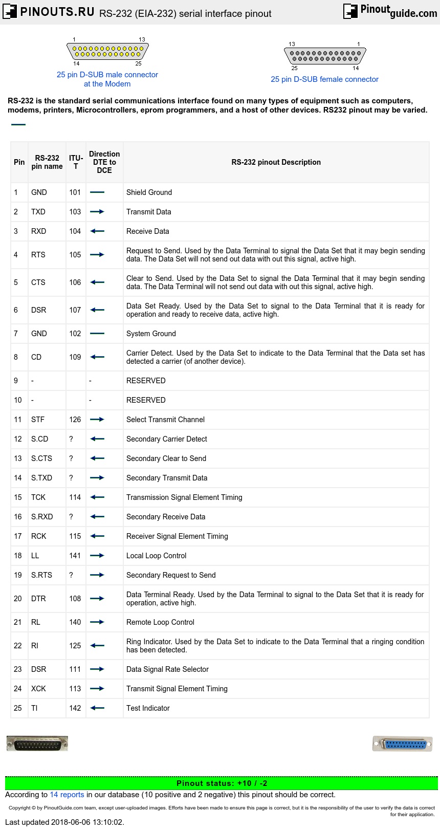
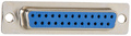
RS-232 standard defines electrical signal characteristics (voltage levels, timing, signaling rate, short-circuit behavior, cable length), mechanical characteristics of RS-232 interface, RS-232 pinouts and connectors, plus some other details. RS-232 data transmission consist of time-series of bits. Both synchronous and asynchronous transmissions are supported, but asynchronous link sending seven or eight bits packets is most common configuration on PC. RS-232 devices may be classified as Data Terminal Equipment (DTE) or Data Communications Equipment (DCE) - this defines which wires will be sending and receiving each signal. The standard recommended but did not make mandatory the common D-subminiature 25 pin connector. Personal computers are usually equipped with simplified version of RS-232 interface.
RS-232 signals
The RS232 pinout signals are represented by voltage levels with respect to a system common (power / logic ground). The idle state (MARK) has the signal level negative with respect to common, and the active state (SPACE) has the signal level positive with respect to common. RS232 has numerous handshaking lines (primarily used with modems), and also specifies a communications protocol.
The RS-232 interface presupposes a common ground between the DTE and DCE. This is a reasonable assumption when a short cable connects the DTE to the DCE, but with longer lines and connections between devices that may be on different electrical busses with different grounds, this may not be true. RS232 data is bi-polar. The standard specifies a maximum open-circuit voltage of 25 volts, but common signal levels are 5 V, 10 V, 12 V, and 15 V. Circuits driving an RS-232-compatible interface must be able to withstand indefinite short circuit to ground or to any voltage level up to 25 volts. From +3 to +12 volts indicates an ON or 0-state (SPACE) condition while A -3 to -12 volts indicates an OFF 1-state (MARK) condition. Some computer equipment ignores the negative level and accepts a zero voltage level as the OFF state. In fact, the ON state may be achieved with lesser positive potential. This means circuits powered by 5 VDC are capable of driving RS232 circuits directly, however, the overall range that the RS232 signal may be transmitted/received may be dramatically reduced. The output signal level usually swings between +12V and -12V. The dead area between +3v and -3v is designed to absorb line noise. In the various RS-232-like pinout definitions this dead area may vary. For instance, the definition for V.10 has a dead area from +0.3v to -0.3v. Many receivers designed for RS-232 are sensitive to differentials of 1v or less.
RS232 pinout
| Pin | RS-232 pin name | ITU-T | Direction DTE to DCE |
RS-232 pinout Description |
|---|---|---|---|---|
| 1 | GND | 101 | Shield Ground | |
| 2 | TXD | 103 |  |
Transmit Data |
| 3 | RXD | 104 |  |
Receive Data |
| 4 | RTS | 105 | |
Request to Send. Used by the Data Terminal to signal the Data Set that it may begin sending data. The Data Set will not send out data with out this signal, active high. |
| 5 | CTS | 106 | |
Clear to Send. Used by the Data Set to signal the Data Terminal that it may begin sending data. The Data Terminal will not send out data with out this signal, active high. |
| 6 | DSR | 107 | |
Data Set Ready. Used by the Data Set to signal to the Data Terminal that it is ready for operation and ready to receive data, active high. |
| 7 | GND | 102 | System Ground | |
| 8 | CD | 109 | |
Carrier Detect. Used by the Data Set to indicate to the Data Terminal that the Data set has detected a carrier (of another device). |
| 9 | - | - | RESERVED | |
| 10 | - | - | RESERVED | |
| 11 | STF | 126 | |
Select Transmit Channel |
| 12 | S.CD | ? | |
Secondary Carrier Detect |
| 13 | S.CTS | ? | |
Secondary Clear to Send |
| 14 | S.TXD | ? | |
Secondary Transmit Data |
| 15 | TCK | 114 | |
Transmission Signal Element Timing |
| 16 | S.RXD | ? | |
Secondary Receive Data |
| 17 | RCK | 115 | |
Receiver Signal Element Timing |
| 18 | LL | 141 | |
Local Loop Control |
| 19 | S.RTS | ? | |
Secondary Request to Send |
| 20 | DTR | 108 | |
Data Terminal Ready. Used by the Data Terminal to signal to the Data Set that it is ready for operation, active high. |
| 21 | RL | 140 | |
Remote Loop Control |
| 22 | RI | 125 | |
Ring Indicator. Used by the Data Set to indicate to the Data Terminal that a ringing condition has been detected. |
| 23 | DSR | 111 | |
Data Signal Rate Selector |
| 24 | XCK | 113 | |
Transmit Signal Element Timing |
| 25 | TI | 142 | |
Test Indicator |
RS-232 connectors
RS-232 devices may be classified as Data Terminal Equipment (DTE) or Data Circuit-terminating Equipment (DCE); this defines at each device which wires will be sending and receiving each signal. According to the standard, male connectors have DTE pin functions, and female connectors have DCE pin functions. Other devices may have any combination of connector gender and pin definitions. Many terminals were manufactured with female connectors but were sold with a cable with male connectors at each end; the terminal with its cable satisfied the recommendations in the standard.
The standard recommends the D-subminiature 25-pin connector up to revision C, and makes it mandatory as of revision D. Most devices only implement a few of the twenty signals specified in the standard, so connectors and cables with fewer pins are sufficient for most connections, more compact, and less expensive. Personal computer manufacturers replaced the DB-25M connector with the smaller DE-9M connector. This connector, with a different pinout, is prevalent for personal computers and associated devices.
Presence of a 25-pin D-sub connector does not necessarily indicate an RS-232-C compliant interface. For example, on the original IBM PC, a male D-sub was an RS-232-C DTE port (with a non-standard current loop interface on reserved pins), but the female D-sub connector on the same PC model was used for the parallel Centronics printer port. Some personal computers put non-standard voltages or signals on some pins of their serial ports.
RS-232 cables
The standard does not define a maximum cable length, but instead defines the maximum capacitance that a compliant drive circuit must tolerate. A widely used rule of thumb indicates that cables more than 15 m long will have too much capacitance, unless special cables are used. By using low-capacitance cables, communication can be maintained over larger distances up to about 300 m. For longer distances, other signal standards are better suited to maintain high speed.
Since the standard definitions are not always correctly applied, it is often necessary to consult documentation, test connections with a breakout box, or use trial and error to find a cable that works when interconnecting two devices. Connecting a fully standard-compliant DCE device and DTE device would use a cable that connects identical pin numbers in each connector (a so-called straight cable). Gender changers are available to solve gender mismatches between cables and connectors. Connecting devices with different types of connectors requires a cable that connects the corresponding pins according to the table below. Cables with 9 pins on one end and 25 on the other are common. Manufacturers of equipment with 8P8C connectors usually provide a cable with either a DB-25 or DE-9 connector (or sometimes interchangeable connectors so they can work with multiple devices).
A minimal 3-wire RS-232 connection consisting only of transmit data, receive data, and ground, is commonly used when the full facilities of RS-232 are not required. Even a two-wire connection (data and ground) can be used if the data flow is one way. When only hardware flow control is required in addition to two-way data, the RTS and CTS lines are added in a 5-wire version.
RS232 pinout details
Data is transmitted and received on pins 2 and 3 respectively. Data Set Ready (DSR) is an indication from the Data Set (i.e., the modem or DSU/CSU) that it is on. Similarly, DTR indicates to the Data Set that the DTE is on. Data Carrier Detect (DCD) indicates that a good carrier is being received from the remote modem.
Pins 4 RTS (Request To Send - from the transmitting computer) and 5 CTS (Clear To Send - from the Data set) are used to control. In most Asynchronous situations, RTS and CTS are constantly on throughout the communication session. However where the DTE is connected to a multipoint line, RTS is used to turn carrier on the modem on and off. On a multipoint line, it's imperative that only one station is transmitting at a time (because they share the return phone pair). When a station wants to transmit, it raises RTS. The modem turns on carrier, typically waits a few milliseconds for carrier to stabilize, and then raises CTS. The DTE transmits when it sees CTS up. When the station has finished its transmission, it drops RTS and the modem drops CTS and carrier together.
Clock signals (pins 15, 17, & 24) are only used for synchronous communications. The modem or DSU extracts the clock from the data stream and provides a steady clock signal to the DTE. Note that the transmit and receive clock signals do not have to be the same, or even at the same baud rate.
RS232 data flow diagram
RS232 data usually is sent as a packet with 7 or 8 bit words, start, stop, parity bits (may be varied). Sample transmission shown on picture: Start bit (active low, usually between +3v and +15v) followed by data bits, parity bit (depends on protocol used) and finished by stop bit (used to bring logic high, usually between -3v and -15v).
+15V	|    0 1 0 0 0 0 0 0 1 0 1 1
	|    _   ___________   _
	|   | | |           | | |
	|   | | |           | | |
	|   | | |           | | |
	|   | | |           | | |
+3V	|   | | |           | | |
0V	|-  | | |     -     | | |      -
-3V	|   | | |           | | |
	|   | | |           | | |
	|   | | |           | | |
	|   | | |           | | |
	|---| |_|           |_| |____-----
        |
-15V	|  Start    Data       P Stop
RS-232 specifications
| SPECIFICATIONS | RS232 | |
|---|---|---|
| Mode of Operation | SINGLE -ENDED |
|
| Total Number of Drivers and Receivers on One Line | 1 DRIVER 1 RECVR |
|
| Maximum Cable Length | 50 FT. | |
| Maximum Data Rate | 20kb/s | |
| Maximum Driver Output Voltage | +/-25V | |
| Driver Output Signal Level (Loaded Min.) | Loaded | +/-5V to +/-15V |
| Driver Output Signal Level (Unloaded Max) | Unloaded | +/-25V |
| Driver Load Impedance (Ohms) | 3k to 7k | |
| Max. Driver Current in High Z State | Power On | N/A |
| Max. Driver Current in High Z State | Power Off | +/-6mA @ +/-2v |
| Slew Rate (Max.) | 30V/uS | |
| Receiver Input Voltage Range | +/-15V | |
| Receiver Input Sensitivity | +/-3V | |
| Receiver Input Resistance (Ohms) | 3k to 7k | |
 correct
 incorrect