The purpose of a null-modem serial cable is to permit two RS-232 devices to communicate with each other without modems or other communication devices between them. To achieve this, the most obvious connection is that the TxD signal of one device must be connected to the RxD input of the other device (and vice versa).
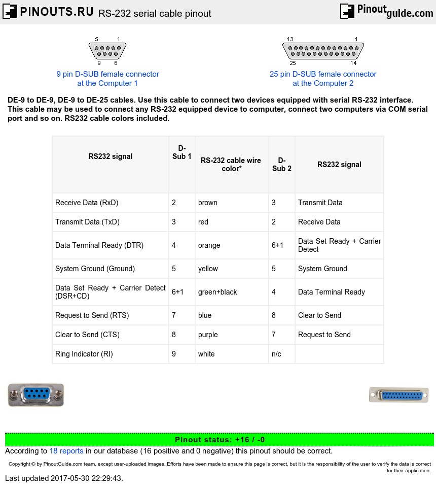
RS-232 serial cable (Null modem) DE-9 to DE-9 with handshake
| RS232 signal |
D-Sub 1 |
RS-232 cable wire color* | D-Sub 2 | RS232 signal |
|---|---|---|---|---|
| Receive Data (RxD) | 2 | brown | 3 | Transmit Data |
| Transmit Data (TxD) | 3 | red | 2 | Receive Data |
| Data Terminal Ready (DTR) | 4 | orange | 6+1 | Data Set Ready + Carrier Detect |
| System Ground (Ground) | 5 | yellow | 5 | System Ground |
| Data Set Ready + Carrier Detect (DSR+CD) | 6+1 | green+black | 4 | Data Terminal Ready |
| Request to Send (RTS) | 7 | blue | 8 | Clear to Send |
| Clear to Send (CTS) | 8 | purple | 7 | Request to Send |
| Ring Indicator (RI) | 9 | white | n/c |
*There is no standard color scheme.
Some devices use other RS-232 pins for flow control. One of the most common schemes is for the DTE (the PC) to assert the RTS signal if it is ready to send data, and DCE (the modem) to assert CTS when it is able to receive data. By connecting the RTS pin of one device to the CTS pin of the other device, we can simulate this handshake.
Also, it is common convention for many devices to assert the DTR signal when they are powered on, and for many DCE devices to assert the DSR signal when they are powered on, and to assert the CD signal when they are connected. By connecting the DTR signal of one DTE to both the CD and DSR inputs of the other DTE (and vice versa), we are able to trick each DTE into thinking that it is connected to a DCE that is powered up and online. As a general rule, the Ring Indicate (RI) signal is not passed through a null-modem connection.
RS-232 serial cable (Null modem) DE-9 to DE-9 without handshake
| RS232 signal |
D-Sub 1 | Cable wire color* | D-Sub 2 | RS232 signal |
|---|---|---|---|---|
| Receive Data (RxD) | 2 | brown | 3 | Transmit Data |
| Transmit Data (TxD) | 3 | red | 2 | Receive Data |
| System Ground (Ground) | 5 | yellow | 5 | System Ground |
*There is no standard color scheme.
Null modem DSUB9 to DSUB25 cable
| D-Sub 9 | D-Sub 25 | ||
|---|---|---|---|
| Receive Data | 2 | 2 | Transmit Data |
| Transmit Data | 3 | 3 | Receive Data |
| Data Terminal Ready | 4 | 6+8 | Data Set Ready + Carrier Detect |
| System Ground | 5 | 7 | System Ground |
| Data Set Ready + Carrier Detect | 6+1 | 20 | Data Terminal Ready |
| Request to Send | 7 | 5 | Clear to Send |
| Clear to Send | 8 | 4 | Request to Send |
Null modem DSUB25 to DSUB25 cable
| D-Sub25 1 | D-Sub25 2 | ||
|---|---|---|---|
| Receive Data | 3 | 2 | Transmit Data |
| Transmit Data | 2 | 3 | Receive Data |
| Data Terminal Ready | 20 | 6+8 | Data Set Ready + Carrier Detect |
| System Ground | 7 | 7 | System Ground |
| Data Set Ready + Carrier Detect | 6+8 | 20 | Data Terminal Ready |
| Request to Send | 4 | 5 | Clear to Send |
| Clear to Send | 5 | 4 | Request to Send |
Note: DSR & CD are jumpered to fool the programs to think that they are online
 correct
 incorrect