
| Pin | Name | Dir | Description |
|---|---|---|---|
| 1 | /XCLK |  |
Extern Clock |
| 2 | /XCLKEN | |
Extern Clock Enable (47 Ohm) |
| 3 | RED |  |
Analog Red (75 Ohm) |
| 4 | GREEN | |
Analog Green (75 Ohm) |
| 5 | BLUE | |
Analog Blue (75 Ohm) |
| 6 | DI | |
Digital Intensity (47 Ohm) |
| 9 | DR | |
Digital Red (47 Ohm) |
| 8 | DG | |
Digital Green (47 Ohm) |
| 7 | DB | |
Digital Blue (47 Ohm) |
| 10 | /CSYNC | |
Composite Sync (47 Ohm) |
| 11 | /HSYNC | |
Horizontal Sync (47 Ohm) |
| 12 | /VSYNC | |
Vertical Sync (47 Ohm) |
| 13 | GNDRTN | Digital Ground (for /XCLKEN) Dont connect with pin 16-20. | |
| 14 | /PIXELSW | |
Genlock overlay (47 Ohm) |
| 15 | /C1 | |
Clock out (47 Ohm) |
| 16 | GND | Video Ground for RED Analog (useful to know because some TVs need specific grounds for specific colors when using SCART/PERITEL SECAM video signal) | |
| 17 | GND | Video Ground for GREEN Analog | |
| 18 | GND | Video Ground for BLUE Analog | |
| 19 | GND | Video Ground for CHV SYNC | |
| 20 | GND | Video Ground | |
| 21 | -12V | |
-12 Volts DC (10 mA max) (A500/A600/A1200) |
| -5V | |
-5 Volts DC (10 mA max) (A1000/A2000/A3000/A4000) | |
| 22 | +12V | |
+12 Volts DC (100 mA max) |
| 23 | +5V | |
+5 Volts DC (100 mA max) |
Note: Direction is Computer relative monitor.
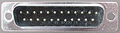
DETAILS FOR MAKING UP A CABLE FOR AMIGA 23-PIN VDU OUTPUT TO AMIGA VGA MONITOR

==============================================================================

END “A1” - THE AMIGA CPU OUTPUT FOR VDU MONITOR IS DB23 MALE SOCKET ON AMIGA CHASSIS

END “B1” - AMIGA MONITOR VDU INPUT IS AN IN-LINE 15-PIN RGB MALE SOCKET ON THE END OF A GROMMETED CABLE BUILT INTO THE VDU CHASSIS


THE CABLE TO JOIN THESE ENDS IS AS FOLLOWS

------------------------------------------

END “A2” - FEMALE DB23 PLUG
END “B2” - FEMALE VGA 15 pin = 3 rows (not 2 row D-type)


“A1” PLUGS INTO “A2”

“B1” PLUGS INTO “B2”


AMIGA CPU to AMIGA VGA MONITOR - CABLE CONNECT

----------------------------------------------

END “A2”      END “B2”

Amiga RGB      VGA RGB

 3 Red Sig      1 Red Sig

 4 Green Sig    2 Green Sig

 5 Blue Sig      3 Blue Sig

19 Video Gnd    5 Gnd

16 Reg Gnd      6 Red Gnd

17 Green Gnd     7 Green Gnd

18 Blue Gnd      8 Blue Gnd

20 Sync Gnd    10 Sync Gnd

11 H Sync       13 H Sync

12 V Sync      14 V sync
 correct
 incorrect