

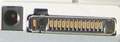
The port contains signals for handsfree microphone, stereo speakers, FBus Rx/Tx or USB signals for the phones supporting them, power output for feeding the accessories that dont have their own batteries, and the Accessory Control Interface (ACI), a bidirectional serial control bus for connection of phone accessories, with a proprietary protocol.
| Pin Number |
Pin Name |
Description |
| 1 | Vin | Charger input |
| 2 | GND | Charger ground |
| 3 | ACI | Accessory Control Interface (short with pin 2 for handsfree recognition) |
| 4 | V Out / VDD+ | Connected to pin 3 in DKU-2 usb data cable / For Hansfree (ex. HS-23): microchip power supply |
| 5 | USB Vbus | Also act as USB power detection? Should be connected to USB pin 1 in usb data cable. (USB Vcc +5V) |
| 6 | FBus Rx/USB D+ | USB exists only in some models*. Should be connected to USB pin 3 in usb data cable. (USB DATA+) |
| 7 | FBus Tx/USB D- | USB exists only in some models*. Should be connected to USB pin 2 in usb data cable. (USB DATA-) |
| 8 | GND | Data GND (USB GND) |
| 9 | X Mic- | Audio in - Ext. Mic input negativ |
| 10 | X Mic+ | Audio in - Ext. Mic input positiv |
| 11 | HS Ear L- | Audio out - Ext. Audio out - left, negativ |
| 12 | HS Ear L+ | Audio out - Ext. Audio out - left, positiv |
| 13 | HS Ear R- | Audio out - Ext. audio out - right, negativ |
| 14 | HS Ear R+ | Audio out - Ext. audio out - right, positiv. Pins 10-14 may be used for antenna connection. |
| GND | shield GND in cavities |
 правильная
 с ошибками