ATX specification includes not only Power Supply Unit, but also interface to case and motherboard. In addition to the old AT standard, ATX 2.0 has one extra voltage line available (+3.3V), a connector chain-lined to the single 20-pin and a power-on wire that allows Software to turn off the PSU. Nowdays this standard is obsolete and superseeded by ATX 2.2 (24 pin).
The ATX specification requires the power supply to produce three main outputs, +3.3 V (±0.165 V), +5 V (±0.25 V) and +12 V (±0.60 V). Low-power −12 V (±1.2 V) and 5 VSB (standby) (±0.25 V) supplies are also required. A −5 V output was originally required because it was supplied on the ISA bus, but it became obsolete with the removal of the ISA bus in modern PCs and has been removed in later versions of the ATX standard.
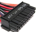
Originally the motherboard was powered by one 20-pin connector. Current version of ATX12V 2.x power supply provides two connectors for the motherboard: a 4-pin auxiliary connector providing additional power to the CPU, and a main 24-pin ATX 2 power supply connector, an extension of the original 20-pin version.
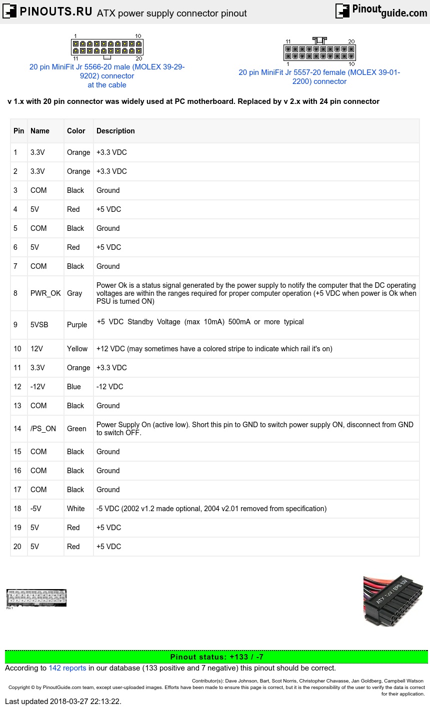
ATX connector pinout
| Pin | Name | Color | Description |
|---|---|---|---|
| 1 | 3.3V | Orange | +3.3 VDC |
| 2 | 3.3V | Orange | +3.3 VDC |
| 3 | COM | Black | Ground |
| 4 | 5V | Red | +5 VDC |
| 5 | COM | Black | Ground |
| 6 | 5V | Red | +5 VDC |
| 7 | COM | Black | Ground |
| 8 | PWR_OK | Gray | Power Ok is a status signal generated by the power supply to notify the computer that the DC operating voltages are within the ranges required for proper computer operation (+5 VDC when power is Ok when PSU is turned ON) |
| 9 | 5VSB | Purple |
+5 VDC Standby Voltage (max 10mA) 500mA or more typical |
| 10 | 12V | Yellow | +12 VDC (may sometimes have a colored stripe to indicate which rail it's on) |
| 11 | 3.3V | Orange | +3.3 VDC |
| 12 | -12V | Blue | -12 VDC |
| 13 | COM | Black | Ground |
| 14 | /PS_ON | Green | Power Supply On (active low). Short this pin to GND to switch power supply ON, disconnect from GND to switch OFF. |
| 15 | COM | Black | Ground |
| 16 | COM | Black | Ground |
| 17 | COM | Black | Ground |
| 18 | -5V | White | -5 VDC (2002 v1.2 made optional, 2004 v2.01 removed from specification) |
| 19 | 5V | Red | +5 VDC |
| 20 | 5V | Red | +5 VDC |
/PS_ON activated by pressing and releasing the power button while the power supply is in standby mode. Shorting the pin 14 (/PS_ON) to GND (COM) causes power supply to switch ON.
In several power supply units pin-12 may be Brown (not Blue), pin-18 may be Blue (not White), and pin-8 may be White (not Gray). In addition, some PSU violate color coding of wires.
Pin 9 (standby) supply 5V even when PSU is turned off. Pin 14 goes from 0 to 3.7 when PSU switch is turned on.
 correct
 incorrect