| Pin | Signal | Description | Apple pin numbering* |
|---|---|---|---|
| 1 | GND | Ground (-), internally connected with Pin 2 on iPod motherboard | 30 |
| 2 | GND | Audio & Video ground (-), internally connected with Pin 1 on iPod motherboard | 29 |
| 3 | Right | Line Out - R (+) (Audio output, right channel) | 28 |
| 4 | Left | Line Out - L(+) (Audio output, left channel) | 27 |
| 5 | Right In | Line In - R (+) | 26 |
| 6 | Left In | Line In - L (+) | 25 |
| 7 | ? | 24 | |
| 8 | Video Out |
Composite video output (only when slideshow active on iPod Photo) or Component Video Pb |
23 |
| 9 | S-Video Chrominance output |
for iPod Color, Photo only or Component Video Y |
22 |
| 10 | S-Video Luminance output |
for iPod Color, Photo only or Component Video Pr |
21 |
| 11 | AUDIO_SW | If connected to GND the iPhone sends audio signals through pin 3-4, otherwise it uses onboard speaker. | 20 |
| 12 | Tx | ipod sending line, Serial TxD | 19 |
| 13 | Rx |
ipod receiving line, Serial RxD |
18 |
| 14 | RSVD | Reserved | 17 |
| 15 | GND | Ground (-), internally connected with pin 16 on iPod motherboard | 16 |
| 16 | GND | USB GND (-), internally connected with pin 15 on iPod motherboard | 15 |
| 17 | RSVD | Reserved | 14 |
| 18 | 3.3V | 3.3V Power (+) Stepped up to provide +5 VDC to USB on iPod Camera Connector. If iPod is put to sleep while Camera Connector is present, +5 VDC at this pin slowly drains back to 0 VDC. |
13 |
| 19,20 | +12V | Firewire Power 12 VDC (+) | 11,12 |
| 21 | Accessory Indicator/Serial enable |
Different resistances indicate accessory type:
|
10 |
| 22 | TPA (-) | FireWire Data TPA (-) | 9 |
| 23 | 5 VDC (+) | USB Power 5 VDC (+) | 8 |
| 24 | TPA (+) | FireWire Data TPA (+) | 7 |
| 25 | Data (-) | USB Data (-) | 6 |
| 26 | TPB (-) | FireWire Data TPB (-) | 5 |
| 27 | Data (+) |
USB Data (+) Pins 25 and 27 may be used in different manners:
Tying either wire to straight to 5V could damage the target - use resistors tied to both 5V and ground to be safe. |
4 |
| 28 | TPB (+) | FireWire Data TPB (+) | 3 |
| 29,30 | GND | FireWire Ground (-) | 1,2 |
*There are two pins numbering schemes for this connector. The one on right column)is from Apple manual. It only became available after publishing of most pinouts and is not used on this site.
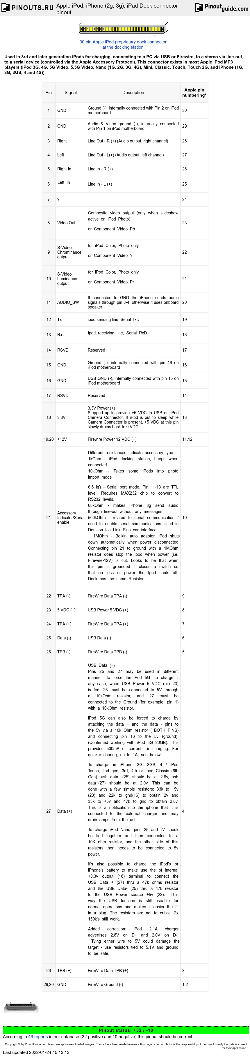
Back side of dock connector;
 2 4 6 8 10 12 14 16 18 20 22 24 26 28 30
 1 3 5 7 9 11 13 15 17 19 21 23 25 27 29
On the iPod motherboard, pins 1&2, 15&16, 19&20, and 29&30 are connected together.
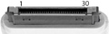
If you disassemble the original apple-ipod-dock-connector-cable and look at the connector itself, on the back side, where it is soldered, you can see the number 1 and 30 (e.g. Pins 1 and 30). In this description the NUMBERING is INVERSED: Pin 1 is Pin 30 and Pin 29 is Pin 2.
Apple Accessory Protocol
The remote control, iTalk and other serial devices use the Apple Accessory Protocol for communication with the iPod. This protocol was introduced with the 3rd generation iPods, and is also compatible with the 4th generation iPods and mini iPods. The connections uses a standard 8N1 (one startbit. 8 data bits, one stop bit) serial protocol, 19200 baud (higher rates up to 57600 are also possible, but speeds faster than 38400 may cause problems with large amounts of data), with a delay of 12 microseconds inserted between the end of the stopbit and the beginning of the next startbit (also works without this delay).
- Electrical: high +3.3V, low 0V
- Default line state: high.
Codes used for communication with peripherals are here
Additional notes
- This device may be connected to the firewire computer port by straight cable (±TPB, ±TPA should be twisted pairs).
- The iPod Nano 4th Gen no longer charges from the 12 V supply on the Firewire pins. If you tie Pins 25 and 27 together and then connect a 10 kOhm resistor to ±5 volts to pins 23 and 15 (or 16), it will charge. If you don't tie Pins 25 and 27 together, it won't charge.
- The iPod Touch 3G: may also require for Pins 1 and 2 (GND and audio out GND) to be connected in order to output audio (Pin 11 to GND). Works with appr. 500 kOhm between pin 21 and GND.
- The iPod Touch 2G requires Pin 11 to be connected to Pins 15/16; then connect that to Pin 21 with a 68 kOhm resistor to use the audio line out. This is because the device needs to be told to redirect the signal to the Line Out pins rather than to the built-in speaker. This explains why certain accessories won't work with the iPod Touch 2G and maybe even the iPod Touch 3G. The iPod nano 5G will require the Pin 11 connection but not the 68 kOhm resistor for redirecting audio. Nano 5G: connecting the 68 kOhm resistor to ground will disable the audio redirection accomplished by connecting Pin 11 to ground.
- You may need to ensure that Pins 1 and 2 are connected to GND for proper charging to occur.
 correct
 incorrect