
RS422 was designed for greater distances and higher Baud rates than RS232. In its simplest form, a pair of converters from RS232 to RS422 (and back again) can be used to form an "RS232 extension cord." Data rates of up to 100K bits / second and distances up to 4000 Ft. can be accommodated with RS422. RS422 is also specified for multi-drop (party-line) applications where only one driver is connected to, and transmits on, a "bus" of up to 10 receivers.
Both RS-422 and RS-485 use a twisted-pair wire (i.e. 2 wires) for each signal. They both use the same differential drive with identical voltage swings: 0 to +5V, but RS-422 is a multidrop standard, allowing for one driver and up to 10 receptors, and rs485 is a multipoint standard, allowing for up to 32 devices (drivers, receivers or transceptors)
Since the basic receivers of RS-423-A and RS422-A are electrically identical, it is possible to interconnect an equipment using RS423-A receivers and generators on one side of the interface with an equipment using RS422-A generators and receivers on the other side of the interface, if the leads of the receivers and generators are properly configured to accommodate such an arrangement and the cable is not terminated.
| Pin | Name | Dir | Description |
|---|---|---|---|
| 1 | GND | Shield Ground | |
| 2 | SRI |  |
Signal Rate Indicator |
| 3 | n/c | - | Spare |
| 4 | SD |  |
Send Data |
| 5 | ST | |
Send Timing |
| 6 | RD | |
Receive Data |
| 7 | RTS | |
Request To Send |
| 8 | RR | |
Receiver Ready |
| 9 | CTS | |
Clear To Send |
| 10 | LL | |
Local Loopback |
| 11 | DM | |
Data Mode |
| 12 | TR | |
Terminal Ready |
| 13 | RR | |
Receiver Ready |
| 14 | RL | |
Remote Loopback |
| 15 | IC | |
Incoming Call |
| 16 | SF/SR | |
Select Frequency/Select Rate |
| 17 | TT | |
Terminal Timing |
| 18 | TM | |
Test Mode |
| 19 | GND | Ground | |
| 20 | RC | Receive Twister-Pair Common | |
| 21 | GND | Spare Twister-Pair Return | |
| 22 | /SD | Send Data TPR | |
| 23 | GND | Send Timing TPR | |
| 24 | /RD | Receive Data TPR | |
| 25 | /RS | Request To Send TPR | |
| 26 | /RT | Receive Timing TPR | |
| 27 | /CS | Clear To Send TPR | |
| 28 | IS | |
Terminal In Service |
| 29 | /DM | Data Mode TPR | |
| 30 | /TR | Terminal Ready TPR | |
| 31 | /RR | Receiver TPR | |
| 32 | SS | |
Select Standby |
| 33 | SQ | |
Signal Quality |
| 34 | NS | |
New Signal |
| 35 | /TT | Terminal Timing TPR | |
| 36 | SB | |
Standby Indicator |
| 37 | SC | Send Twister Pair Common |
RS422 is a balanced serial interface for the transmission of digital data. The advantage of a balanced signal is the greater immunity to noise. The EIA describes RS422 as a DTE to DCE interface for point-to-point connections.
Technical Description
The data is coded as a differential voltage between the wires. The wires are named A (negative) and B (positive). When B >A then the output is a mark (1 or off) and when A >B then it is counted as a space (0 or on).
In general a mark is +1 Vdc for the A line and +4 Vdc for the B line.
A space is +1 Vdc for the B line and +4Vdc for the A line.
At the transmitter end the voltage difference should not be less than 1.5 Vdc and not exceed 5 Vdc.
At the receiver end the voltage difference should not be less than 0.2 Vdc. The minimum voltage level is -7 Vdc and maximum +12 Vdc.
| Max. Distance @ Rate | 1200 meter/ 4000 feet @ max. 100 kbps |
|---|---|
| Max. Rate @ Distance | 10 Mbps @ 12 meter/ 50 ft |
| Driver Output Resistance | 100 ohm |
| Receiver Input Resistance | 4 kohm min. |
| Max. Output Current | 150 mA |
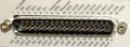
The interface is normally terminated on a 4 wire screw block or on a Sub-D37 (RS449), but other interfaces are not uncommon.
RS449 gets it"s blazing speed from the fact that, unlike RS232 which uses signals with reference to ground, it"s receivers look for the difference between two wires. Now the secret, by twisting these two wires any stray noise picked up on one wire will be picked up on the other, because both wires pick up the same noise the differential just shifts in voltage level with reference to ground, but does not change with respect to each other. Remember the receivers are only looking at the difference in voltage level of each wire to the other not to ground. This is what makes all the new wire interfaces work, V.35, RS530, 10baseT, etc.
The biggest problem faced is how the cables are made
The differential signals for RS449 are labeled as either "A and B" or "+ and -". In the case of RS449 wire A or + does not connect to B or -. Wire A always connects to A and B connects to B or + to + and - to -. If you do cross the wires you just inverted the data or clock in your interface. I have never seen any piece of equipment damaged from this, but they don"t work this way either.
Some specs:
| SPECIFICATIONS | RS423 | RS422 | |
|---|---|---|---|
| Mode of Operation | SINGLE - ENDED | DIFFERENTIAL | |
| Total Number of Drivers and Receivers on One Line | 1 DRIVER 10 RECVR |
1 DRIVER 10 RECVR |
|
| Maximum Cable Length | 4000 FT. | 4000 FT. | |
| Maximum Data Rate | 100kb/s | 10Mb/s | |
| Maximum Driver Output Voltage | +/-6V | -0.25V to +6V | |
| Driver Output Signal Level (Loaded Min.) | Loaded | +/-3.6V | +/-2.0V |
| Driver Output Signal Level (Unloaded Max) | Unloaded | +/-6V | +/-6V |
| Driver Load Impedance (Ohms) | >450 | 100 | |
| Max. Driver Current in High Z State | Power On | N/A | N/A |
| Max. Driver Current in High Z State | Power Off | +/-100uA | +/-100uA |
| Slew Rate (Max.) | Adjustable | N/A | |
| Receiver Input Voltage Range | +/-12V | -10V to +10V | |
| Receiver Input Sensitivity | +/-200mV | +/-200mV | |
| Receiver Input Resistance (Ohms) | 4k min. | 4k min. | |

 правильная
 с ошибками