| Pin Number |
Pin Name |
Description (may be empty) |
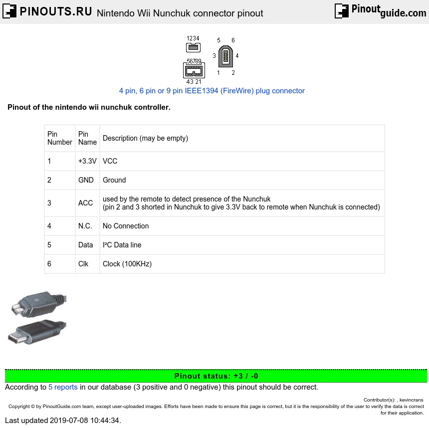
| 1 | +3.3V | VCC |
| 2 | GND | Ground |
| 3 | ACC | used by the remote to detect presence of the Nunchuk (pin 2 and 3 shorted in Nunchuk to give 3.3V back to remote when Nunchuk is connected) |
| 4 | N.C. | No Connection |
| 5 | Data | I²C Data line |
| 6 | Clk | Clock (100KHz) |
*Wii peripheral Protocol is 400kHz fast I2C, with slave address 0x52.
The Nunchuk is identified by the 16-bit constant 0x0000 (0xFEFE encrypted) at register address 0xa400fe. It provides three-axis acceleration data, two digital buttons, and an X-Y analog stick.
Data Format (Nunchuk)
The Nunchuk reports its information as 6 bytes of data, readable at 0xa40008 and streamable using Data Reporting Modes that include Extension bytes (unused bytes are filled with 0x00). The data is packed into the six bytes as follows (after decryption):
| Bit | ||||||||
| Byte | 7 | 6 | 5 | 4 | 3 | 2 | 1 | 0 |
| 0 | SX<7:0> | |||||||
| 1 | SY<7:0> | |||||||
| 2 | AX<9:2> | |||||||
| 3 | AY<9:2> | |||||||
| 4 | AZ<9:2> | |||||||
| 5 | AZ<1:0> | AY<1:0> | AX<1:0> | BC | BZ | |||
SX,SY are the Analog Stick X and Y positions, while AX, AY, and AZ are the 10-bit accelerometer data (in the same format as described in Wiimote#Accelerometer).
The values returned by the analog stick in the nunchuk enclosure do not encompass the full possible range, but rather have upper and lower bounds. These bounds seem to be in the same range across Nunchuks, but there is some variation. Analog stick X returns data from around 35 (fully left) to 228(fully right), while analog stick Y returns from around 27 to 220. Center for both is around 128.
The accelerometer data uses the full range of 0-1024. However, the full range is only seen when moving or rotating the Nunchuk sharply. To measure still Nunchuk rotation in space, the following approximate bounds apply: X goes from around 300 (fully tilted left) to 740 (tilted right), turning further starts bringing the value closer to 512 (neutral position). Similarly, Y goes from around 280 (tilted backwards) to 720 (forwards). Z goes from 320 (upside-down) to 760 (right-side up).
BC and BZ are the state of the C and Z buttons (0=pressed).
Nintendo games calibrate the center position of the Analog Stick upon power-up or insertion of the Nunchuk. The mechanism for that is unknown.
 correct
 incorrect