Hardware pinouts information and cables schemes

IDE cable pinout

hard disks cables wiring

bookmark this page

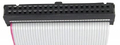
The IDE interface requires only one cable. All pins straight from 1 to 1, 2 to 2 and so on. The drives can be connected in any order. Only remember that one should be jumpered as Master and the other as Slave. If only one drive is used, jumper it as Single (if such a mode exists, or most common Master else).

Controller         Drive 1 or 2   Drive 1 or 2
+--+                   +--+            +--+
|::|===================|::|============|::|  <-Pin 1
|::|===================|::|============|::|
|::|===================|::|============|::|
|::|===================|::|============|::|
|::|===================|::|============|::|
|::|===================|::|============|::|
|::|===================|::|============|::|
+--+                   +--+            +--+
Controller Drive 1 Drive 2
Wire 1-401-401-401-40

Want to add or correct something here? Edit this page!
40 pin IDC female connector layout
40 pin IDC female connector
at the Drive 1 & Drive 2
Pinouts.ru > Disk drives cables schemes listing > Pinout of IDE cable and layout of 40 pin IDC female connector and 40 pin IDC female connector
Is it correct?:
should be correct
Source(s) of this and additional information: Hardware Book
6 reports
Last updated 2008-06-28 21:56:54. Edit this page. Is this document correct or incorrect? What is your opinion?
[Discuss at the forum] [Back to index] [SUBMIT new pinout]
This page contain parts under Copyright © 2000-2008 by pinouts.ru team.
No any portion of this webpage may be reproduced in any form without visible direct link to this page provided. Webmaster permission required in any other cases.
Efforts have been made to ensure this page is correct, but it is the responsibility of the user to verify the data is correct for their application.
40187 hits since March 4, 2005