
| Pin | Name | Dir | Description |
|---|---|---|---|
| 1 | /RESET |  |
Reset |
| 2 | GND | Ground | |
| 3 | DD7 |  |
Data 7 |
| 4 | DD8 | |
Data 8 |
| 5 | DD6 | |
Data 6 |
| 6 | DD9 | |
Data 9 |
| 7 | DD5 | |
Data 5 |
| 8 | DD10 | |
Data 10 |
| 9 | DD4 | |
Data 4 |
| 10 | DD11 | |
Data 11 |
| 11 | DD3 | |
Data 3 |
| 12 | DD12 | |
Data 12 |
| 13 | DD2 | |
Data 2 |
| 14 | DD13 | |
Data 13 |
| 15 | DD1 | |
Data 1 |
| 16 | DD14 | |
Data 14 |
| 17 | DD0 | |
Data 0 |
| 18 | DD15 | |
Data 15 |
| 19 | GND | Ground | |
| 20 | KEY | - | Key (Pin missing) |
| 21 | DMARQ |  |
DMA Request |
| 22 | GND | Ground | |
| 23 | /DIOW | |
Write Strobe |
| 24 | GND | Ground | |
| 25 | /DIOR | |
Read Strobe |
| 26 | GND | Ground | |
| 27 | IORDY | |
I/O Ready |
| 28 | SPSYNC:CSEL | ? | Spindle Sync or Cable Select. Hasn't been used for spindle sync in probably decades now. It is grounded at the host; if a drive sees this pin grounded and has its CS jumper installed, it is the master/device 0, if it sees the pin floating and has its CS jumper installed, it is the slave/device 1. |
| 29 | /DMACK | |
DMA Acknowledge |
| 30 | GND | Ground | |
| 31 | INTRQ | |
Interrupt Request |
| 32 | /IOCS16 | |
IO ChipSelect 16. During a PIO operation it signifies the data transaction in process needs to be a 16 bit value. In DMA operations, it is never asserted, even though they are all 16 bit. |
| 33 | DA1 | |
Address 1 |
| 34 | PDIAG | ? | Passed Diagnostics. Is grounded by the cable when an 80 pin cable is installed, or wired through to the drives with a 40 pin cable |
| 35 | DA0 | |
Address 0 |
| 36 | DA2 | |
Address 2 |
| 37 | /IDE_CS0 | |
(1F0-1F7) |
| 38 | /IDE_CS1 | |
(3F6-3F7) |
| 39 | /ACTIVE | |
Led driver |
| 40 | GND | Ground | |
| 41 | +5VL | +5 VDC (Logic) | |
| 42 | +5VM | +5 VDC (Motor) | |
| 43 | GND | Ground | |
| 44 | /TYPE | Type (0=ATA) |
Note: Direction is Controller relative Devices (harddisks).
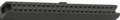
Special Note: Pin 1 is closest to the 4-pin selector. Pin 20 may be missing, this is normal, and allows for cable polarity.
On some motherboards, pin 1 is usually indicated by a Square or Triangle, either on the solder pad, above label, or silkscreen markings.
 correct
 incorrect