PoE integrates data and power on the same wires, while keeping the structured cabling safe and not interfering with concurrent network operation. PoE delivers 44-57v of DC power over unshielded twisted-pair wiring for terminals consuming up to 25 watts, depending on the version of the standard in use. There are several common techniques for transmitting power over Ethernet cabling; two of them have been standardized by the IEEE 802.3 committee. Power may be transmitted on the unused (spare) conductors of a cable, since only two of the four pairs are needed for the commonly used 10Mbit/s–100Mbit/s physical layers (Alternative B) or power may be transmitted on the data conductors by applying a common-mode voltage to each pair (Alternative A).
The IEEE standards for PoE require category 5 cable or better for high power levels but allow using category 3 cable if less power is required. Power is supplied in common mode over two or more of the differential pairs of wires found in the Ethernet cables and comes from a power supply within a PoE-enabled networking device such as an Ethernet switch or can be injected into a cable run with a midspan power supply. A midspan power supply, also known as a PoE power injector, is an additional PoE power source that can be used in combination with a non-PoE switch.
Standards-based Power over Ethernet is implemented following the specifications in IEEE 802.3af-2003. A phantom power technique is used to allow the powered pairs to also carry data. This permits its use not only with 10BASE-T and 100BASE-TX, which use only two of the four pairs in the cable, but also with 1000BASE-T (gigabit Ethernet), which uses all four pairs for data transmission. This is possible because all versions of Ethernet over twisted pair cable specify differential data transmission over each pair with transformer coupling; the DC supply and load connections can be made to the transformer center-taps at each end. Each pair thus operates in common mode as one side of the DC supply, so two pairs are required to complete the circuit. The polarity of the DC supply may be inverted by crossover MDI-X cables; the powered device must operate with either pair: spare pairs 4–5 and 7–8 or data pairs 1–2 and 3–6. Polarity is required on data pairs, and ambiguously implemented for spare pairs, with the use of a diode bridge.
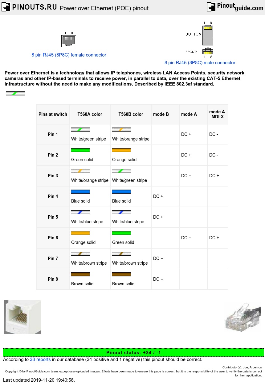
IEEE 802.3af standard POE pinout:
| Pins at switch | T568A color | T568B color | mode B | mode A | mode A MDI-X |
|---|---|---|---|---|---|
| Pin 1 |  White/green stripe |
 White/orange stripe |
DC + | DC - | |
| Pin 2 |  Green solid |
 Orange solid |
DC + | DC - | |
| Pin 3 | White/orange stripe |
White/green stripe |
DC − | DC + | |
| Pin 4 |  Blue solid |
DC + | ||
| Pin 5 |  White/blue stripe |
DC + | ||
| Pin 6 | Orange solid |
Green solid |
DC − | DC + | |
| Pin 7 |  White/brown stripe |
DC − | ||
| Pin 8 |  Brown solid |
DC − |
IEEE Std 802.3-2015 table 33-2 also allows PSE side Alternative A (MDI-X) with polarity reversed from Alternative A (MDI).
The original IEEE 802.3af-2003 PoE standard devices provides up to 15.4 W of DC power (minimum 44 V DC and 350 mA) to each device.
The newer PoE+ IEEE 802.3at-2009 PoE standard provides up to 25.5 W of power. Some vendors have announced products that offer up to 51 W of power over a single cable by utilizing all four pairs in the Category 5 cable.
| Property | 802.3af (802.3at Type 1)PoE | 802.3at Type 2 PoE+ | 802.3bt Type 3 4PPoE | 802.3bt Type 4 |
|---|---|---|---|---|
| Power available at PD | 12.95 W | 25.50 W | 51 W | 71 W |
| Maximum power delivered by PSE | 15.40 W | 30.0 W | 60 W | 100 W |
| Voltage range (at PSE) | 44.0–57.0 V | 50.0–57.0 V | 50.0–57.0 V | 52.0–57.0 V |
| Voltage range (at PD) | 37.0–57.0 V | 42.5–57.0 V | 42.5–57.0 V | 41.1–57.0 V |
| Maximum current Imax | 350 mA | 600 mA | 600 mA per pair | 960 mA per pair |
| Maximum cable resistance per pairset | 20 Ω (Category 3) | 12.5 Ω (Category 5) | 12.5 Ω | 12.5 Ω |
| Power management | Three power class levels negotiated by signature | Four power class levels negotiated by signature or 0.1 W steps negotiated by LLDP | Three power class levels negotiated by signature or 0.1 W steps negotiated by LLDP | 0.1 W steps negotiated by LLDP |
| Supported cabling | Category 3 and Category 5 | Category 5 | Category 5 | Category 5 |
| Supported modes | Mode A (endspan), Mode B (midspan) | Mode A, Mode B | Mode A, Mode B, 4-pair mode | 4-pair mode |
POE device-specific pinouts:
| STANDARD | SOURCE | LOAD | REMARKS | |||||||||
|---|---|---|---|---|---|---|---|---|---|---|---|---|
| Ethernet RJ-45 connector pin number | ||||||||||||
| Source Voltage | 1 | 2 | 3 | 4 | 5 | 6 | 7 | 8 | Load Voltage | DC Load Connector | ||
| IEEE 802.3af using data pairs |
48 V DC, protected | RX, DC+ | RX, DC+ | TX, DC- | spare | spare | TX, DC- | spare | spare | (embedded) | Industry Standard for active PoE | |
| IEEE 802.3af using spare pairs |
48 V DC, protected | RX | RX | TX | DC+ | DC+ | TX | DC- | DC- | (embedded) | Industry Standard for passive PoE | |
| Intel, Symbol, Orinoco | Usually 12 or 24 V DC |
RX | RX | TX | DC+ | DC+ | TX | DC- | DC- | (embedded) | Most Brands of PoE | |
| Cisco (OLD old standard) |
48 V DC | RX | RX | TX | DC- | DC- | TX | DC+ | DC+ | (embedded) | Older Cisco polarity is REVERSED |
|
| Cisco (NEW old standard) |
48 V DC | RX | RX | TX | DC+ | DC+ | TX | DC- | DC- | (embedded) | New Cisco is IEEE compliant | |
|
Cisco (very unusual) |
28 V DC | DC+ | DC- | TX | n.c. | n.c. | TX | RX | RX | (embedded) | Seen on Cisco 7936 conference station, also worked with Polycom SoundStation IP 4000 with 19V source power | |
| D-Link (Adapter) | 48 V DC | RX | RX | TX | DC+ | DC+ | TX | DC- | DC- |
5VDC @ 2.5A |
DC coaxial 5.5/2.5mm |
D-Link PoE Adapter for non-PoE products. |
| Apple MacIntosh AirPort PoE, Extreme | 48 V DC | RX | RX | TX | DC? | DC?? | TX | DC?? | DC?? | Converted to ??? | DC coaxial (???) |
Mac Polarity Unknown |
| HyperLink | Many DC Voltages Available | RX | RX | TX | DC+ | DC+ | TX | DC- | DC- | same as input | DC coaxial and others available | Variety of Options Available to Fit Most Brands of PoE |
| NYC Wireless Roll Your Own |
12 or 24 or 48 V DC | RX | RX | TX | DC+ | DC+ | TX | DC- | DC- | same as input | DC coaxial or as reqd |
New York City Wireless PoE |
| 3Com AirConnect | 24 V DC | RX | RX | TX | spare | spare | TX | DC+ | DC- | 3Com AirConnect wireless access points | ||
| Alvarion VL | 55 Vdc | RX | RX | TX | DC+ | DC- | TX | DC+ | DC- | |||
| TP-link TL-SF1008P | DC- | DC- | DC+ | DC+ | ||||||||
| Polycom IP500 / 501 | 12V DC | RX | RX | TX | DC- | DC- | TX | DC+ | DC+ | The only difference between regular PoE injectors and the Polycom one is the inverted polarity. | ||
PoE - powered devices should obey following specifications:
| Parameter | Min | Max |
| Signature Resistance, KOhm | 23.75 | 26.25 |
| Startup Time (till I>10mA), ms | 300 | |
| Operating Input Voltage Range, V | 36 | 57 |
| Must Turn on Voltage, V | 44 | |
| Must Turn off Voltage, V | 30 V | |
| Input Current (@36Vdc), mA | 10 | 350 |
| Input Current, Peak, mA | 400 |
Maximum length of the cable PoE UTP 5cat.
Input Voltage 9 V: < 30 m
Input Voltage 12 V: < 60 m
Input Voltage 24 V and more answers the quality IEEE 802.3af standard.
 correct
 incorrect