| Pin | Name | Dir | Description |
|---|---|---|---|
| 1 | /RDY | Disk Ready | |
| 2 | /DKRD | Disk Read Data | |
| 3 | GND | Ground | |
| 4 | GND | Ground | |
| 5 | GND | Ground | |
| 6 | GND | Ground | |
| 7 | GND | Ground | |
| 8 | /MTRXD | OC | Disk Motor Control |
| 9 | /SEL2 | OC | Select Drive 2 |
| 10 | /DRES | OC | Disk Reset |
| 11 | /CHNG | Disk Removed From Drive-Latched Low | |
| 12 | +5V | +5 Volts DC (250 mA max) | |
| 13 | /SIDE | Select Disk Side (0=Upper, 1=Lower) | |
| 14 | /WPRO | Disk is Write Protected | |
| 15 | /TKO | Drive Head position over Track 0 | |
| 16 | /DKWE | OC | Disk Write Enable |
| 17 | /DKWD | OC | Disk Write Data |
| 18 | /STEP | OC | Step the Head-Pulse, First low, then high |
| 19 | DIR | OC | Select Head Direction (0=Inner, 1=Outer) |
| 20 | /SEL3 | OC | Select Drive 3 |
| 21 | /SEL1 | OC | Select Drive 1 |
| 22 | /INDEX | OC | Disk Index Pulse |
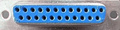
| 23 | +12V | +12 Volts DC (160 mA max, 540 mA surge |
hard drive connector

 correct
 incorrect