
IBM/PC pinout (common PCs): Note: All Odd Numbered Pins Are GROUND see text
| Pin | Name | Dir | Description |
|---|---|---|---|
| 2 | /REDWC | Density Select. PC tells floppy drive what speed is needed (and in reality later floppy drives don't need this info as they automatically read it from floppy hd/dd hole) | |
| 4 | n/c | Reserved | |
| 6 | n/c | Reserved | |
| 8 | /INDEX |  |
Index |
| 10 | /MOTEA |  |
Motor Enable A |
| 12 | /DRVSB | |
Drive Sel B |
| 14 | /DRVSA | |
Drive Sel A |
| 16 | /MOTEB | |
Motor Enable B |
| 18 | /DIR | |
Direction |
| 20 | /STEP | |
Step |
| 22 | /WDATE | |
Write Data |
| 24 | /WGATE | |
Floppy Write Enable |
| 26 | /TRK00 | |
Track 0 |
| 28 | /WPT | |
Write Protect |
| 30 | /RDATA | |
Read Data |
| 32 | /SIDE1 | |
Head Select |
| 34 | /DSKCHG | |
Disk Change/Ready |
Floppy Diskdrive pinout (Shugart interface):
| Pin | Name | Dir | Description |
|---|---|---|---|
| 2 | /DCD | |
Disk Change Detect |
| 3 | Key | no pin in this position | |
| 6 | /DS3 | Device Select 3. Not sure but Amiga 500s schematics reveal that this signal might be used for motor control of internal DF1: on the Amiga 2000 | |
| 4 | /INUSE | A common open-collector LED driver signal? I have never seen this signal used anywhere. | |
| 8 | /INDEX | |
Index |
| 10 | /DS0 | |
Device Select 0 |
| 12 | /DS1 | |
Drive Sel B |
| 14 | /DS2 | |
Device Select 2 |
| 16 | /MTRON | |
Motor On |
| 18 | /DIR | |
Direction |
| 20 | /STEP | |
Step |
| 22 | /WDATE | |
Write Data |
| 24 | /WGATE | |
Floppy Write Enable |
| 26 | /TRK00 | |
Track 0 |
| 28 | /WPT | |
Write Protect |
| 30 | /RDATA | |
Read Data |
| 32 | /SIDE1 | |
Head Select |
| 34 | /RDY | |
Drive Ready/Disk Changed |
On a standard floppy drive there is absolutely no way to remap the motor on signal to another pin with jumpers. Therefore to have independent motor control for two drives the cable must provide this remapping with the traditional seven-conductor twist. If you jumper a floppy drive to work as drive A (unit 0) and connect it to an IBM PC controller with a direct cable, the drive will be selected when the controller tries to turn on the motor of drive A but nothing will happen and the drives motor will rotate when drive Bs motor is turned on.
The original Shugart interface (from which the IBM PC floppy interface is derived a long time ago) doesnt have separate motor on signals for the floppy drives but it does have a total of four device select lines. I have also seen floppy drives that wont turn on their motors unless the according device select signal is driven low. My guess is that this kind of drives strictly follow the original Shugart standard.
Also many synthesizers that have floppy drives use the standard Shugart interface pinout. This is why after replacing a faulty drive many people ask around the Internet why their new floppy drive doesnt work when connected to the synth but works fine on their PC.
The same thing affects the classic Amiga. It uses a very slightly modified Shugart interface pinout at the motherboard (the other /MTRON on pin 4) and a PC drive just doesnt work correctly unless the /DCD is remapped to its original pin. The correctly mapped /DCD is enough for AmigaOS but many trackloaders (X-Copy Pro for example) require the /RDY signal which the drive should set low when the motor rotation has stabilised. This signal does exist on most drives but at worst it requires relocating a soldered SMD jumper on the circuit board.
The floppy cable has 34 wires. There are normally five connectors on the floppy interface cable, although sometimes there are only three. These are grouped into three sets; a single connector plus two pairs of two each (for a standard, five-connector cable) or three single connectors. This how the connectors are used:
| Controller Connector: The single connector on one end of the cable is meant to connect to the floppy disk controller, either on a controller card or the motherboard. | |
| Drive A Connectors: The pair of connectors (or single connector in the case of a three-connector cable) at the opposite end of the cable is intended for the A: floppy drive. This is explained in more detail below. | |
| Drive B Connectors: The pair of connectors (or single connector in the case of a three-connector cable) in the middle of the cable is intended for the B: floppy drive. |
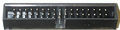
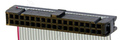
The reason that the standard cable uses pairs of connectors for the drives is for compatibility with different types of drives. 3.5 drives generally use a pin header connector, while 5.25 drives use a card edge connector. Therefore, each position, A and B, has two connectors so that the correct one is available for whatever type of floppy drive being used. Only one of the two connectors in the pair should be used (they're too close together to use both in most cases anyway). The more common pin header (IDC) connector is shown below.
The three-connector cables are found either in very old systems or in ones where the manufacturer was trying to save a few pennies. They reduce the flexibility of the setup; fortunately these cables can be replaced directly by the five-connector type if necessary.
You will also notice that there is an odd twist in the floppy cable, located between the two pairs of connectors intended for the floppy drives. Despite the fact that this appears to be a hack (well, it really is a hack), this is in fact the correct construction of a standard floppy interface cable. There are some cables that do not have the twist, and it is these that are actually non-standard! What the twist does it to change the connection of the drive on the far end of the twist so that it is different than the drive before the twist. This is done to cause the drive at the end of the cable to appear as A: to the system and the one in the middle to be as B:.
Heres how it works in detail. Traditionally, floppy drives used a drive select (DS) jumper to configure the drive as either A: or B: in the system. Then, special signals were used on the floppy interface to tell the two drives in the system which one the controller was trying to talk to at any given time. The wires that are cross-connected via the twist are signals 10 to 16 (seven wires). Of these, 11, 13, and 15 are grounds and carry no signal, so there are really four signals that are inverted by the twist. The four signals that are inverted are exactly the ones that control drive selection on the interface. Here is what happens when the twisted cable is used:
| Line 10 | Line 12 | Line 14 | Line 16 | |
| Controller Signals | Motor Enable A | Drive Select B | Drive Select A | Motor Enable B |
| Drive Before the Twist Sees | Motor Enable A | Drive Select B | Drive Select A | Motor Enable B |
| Drive After the Twist Sees | Motor Enable B | Drive Select A | Drive Select B | Motor Enable A |
Since the signals are inverted, the drive after the twist responds to commands backwards from the way it should; if it has its drive select jumpers set so that it is an A: device, it responds to B: commands, and vice-versa.
One might ask why the twist was needed. In short, because it was a big time-saver during setup back in the days when it was quite common to find two floppy drives in a machine. Without the twist, for two floppy drives to be used, one had to be jumpered as A: and the other as B:. With the twist, it was possible to leave them both jumpered as B:, and whichever was after the twist will appear to the system as A: because the control lines are inverted. Changing which drive is A: and which is B: is as easy as switching the cable. In systems with only one floppy drive, only the connector after the twist cable should be used. Large manufacturers, therefore, could arrange to have all of their floppy disks configured the same way without having to pull jumpers as the PC was assembled.
In order for this system to work, both drives must be jumpered as B: drives. Since the floppy cable with the twist is standard, this jumpering scheme has become the standard as well. Virtually all floppy disks that you purchase come pre-jumpered as B: drives so that they will work with this setup.
If this whole idea sounds similar to the seldom-used cable select protocol for IDE/ATA hard disks, thats because it is essentially the same thing. IDE/ATA hard disks require you to change the master/slave jumpers in a similar manner, and cable select was invented to do away with this. The difference is, as usual, just one of inertia and history; the floppy drive system is the standard while cable select never caught on for hard disks.
Some newer BIOSes have taken things a step further. They include a BIOS parameter that will invert the A: and B: signals within the controller itself. When enabled, this lets you reverse whichever drive is A: with the one that is B:, without requiring you to even open the case. Note however that this is not compatible with all operating systems: in particular, both Windows NT and Linux can malfunction with this swap feature set, which can cause serious problems when trying to install the operating system. The reason this happens is that the swap setting only affects the way the BIOS handles the floppy drive, and confuses operating systems that go directly to the hardware.
Apparently, there is yet another floppy cable variant out there, that is used by some manufacturers. In this setup, there are actually two twists in the floppy cable. The drive placed after the first twist, in the middle of the cable, is A:, much as it is with the standard one-twist cable. The drive placed after the second twist is B:. The second twist reverses the effect of the first one and makes the connector at the end of the cable operate the same way a drive that appears before the twist in a regular cable does.
On some mainboards pin 3 is used as the key (missing pin) and on some pin 5 is used as the key pin, while a lot of mainboards dont have the key pin removed at all. This can all cause problems when using cables which have the key pin hole closed. As all odd pins are ground there are no technical implications in modifying such cables by removing the key pin closure by force.
Note: Direction is Computer relative Diskdrive.
Note: All odd pins are GND, Ground.
Note: Can be an Edge-connector on old PC´s.
 correct
 incorrect