

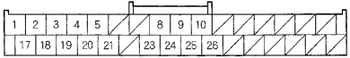
| Pin Number |
Harness color | Pin Name |
Description |
|---|---|---|---|
| 1 | WHT | R SIG 1 | Red color signal |
| 2 | RED | G SIG 1 | Green color signal |
| 3 | GRY | SH SIG 1 | Shield for terminals No. 1,2,17,18,19 |
| 4 | GRN | AC-SI | Communication signal for climate control unit |
| 5 | GRY | ILL+ | Parking light on signal |
| 8 | WHT | CAN-H | F-CAN bus communication |
| 9 | GRY | SH ECU BUS | Shield for display bus No. 10,26 terminal |
| 10 | GRN | ECU BUS+ | Data bus+ GA-NET |
| 17 | YEL | B SIG 1 | Blue color signal |
| 18 | BRN | C SIG 1 | Composite video (vertical/horizontal) Synchronizing signal |
| 19 | BLU | GND SIG 1 | Ground for color signal |
| 20 | PUR | AC-SO | Communication signal for climate control unit |
| 21 | BRN | AC-CLK | Check signal for climate control unit |
| 23 | WHT | JOG | Interface dial operation signal (0—5 V pulses) |
| 24 | RED | CAN-L | F-CAN bus communication |
| 25 | GRY | SH JOG | Shield for interface dial signal |
| 26 | RED | ECU BUS- | Display bus negative. If open: Navigation buttons do not work. |
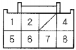
| Pin Number |
Harness color | Pin Name |
Description |
|---|---|---|---|
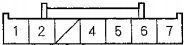
| 1 | WHT | +B | Battery voltage |
| 2 | PUR | ACC | Battery voltage at ACC (I) |
| 4 | BLK | GND | |
| 5 | BRN | BACK LT | Back light or reverse signal. In reverse, battery voltage: Otherwise 0 V |
| 6 | BLU | VSP | 0—5 V pulses average 2.5 V (Depending on bus traffic) |
| 7 | GRN | DIAG+ | Service check signal for navigation system. If short to ground: System goes into diagnostic mode at key ON (I) and (II). |
| 8 | YEL | DIAG- | If open: The system will not go into diagnostic mode when using the SCS jumper. |
| Pin Number |
Harness color | Pin Name |
Description |
|---|---|---|---|
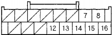
| 7 | RED | RG L+ | Left audio signal of voice guidance, and Voice Recognition (VR) prompts |
| 8 | GRN | MIC SIG+ | Microphone output signal positive |
| 12 | PUR | STRG SW | Steering switch output |
| 13 | GRY | RG L SH | Shield for terminals No. 7,14 |
| 14 | GRN | RG L GND | Ground for voiceguidance, andVoice Recognition (VR) prompts |
| 15 | GRY | SH MIC | Shield for terminals No. 8,16 |
| 16 | RED | MIC SIG- | Ground for microphone signal |
| Pin Number |
Harness color | Pin Name |
Description |
|---|---|---|---|
| 1 | WHT | RC VCC | Power source for rearview camera (8V) |
| 2 | BLK | RC GND | Ground for rearview camera |
| 3 | RED | Camera GND | Ground for rearview camera video signal |
| 5 | YEL | Camera V | Video signal for rearview camera |
| 6 | GRY | Camera SH | Shield for terminals No. 1,2, 4,5,7 |
| 7 | GRN | Camera (ADPT) | Control signal for rearview camera (0-1V) |
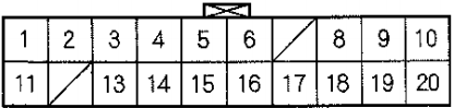
20 pin connector at the display unit (p/n 39810-SJA-A04, 39810-SJA-305, 39810-SJA-A011?)
| Pin Number |
Harness color | Pin Name |
Description |
|---|---|---|---|
| 1 | WHT | +B | Continuous power source |
| 2 | PUR | ACC | Power source for accessory |
| 3 | GRN | GA-NET BUS+ | Data bus+ GA-Net |
| 4 | GRY | GA-NET BUS SH | Shield for terminals No. 3,13 |
| 5 | GRN | ECU BUS+ | Data bus+ GA-Net |
| 6 | LT GRN | SECURITY+ | Security signal to rear screen |
| 8 | WHT | R SIG 1 | Red color signal |
| 9 | RED | G SIG 1 | Green color signal |
| 10 | BLK | GND | Ground for display unit |
| 11 | LT BLU | ILL+ | Parking light on signal from dash and console lights |
| 13 | RED | GA-NET BUS- | Data bus - GA-Net |
| 14 | GRY | SH ECU BUS | Shield for display bus terminals No. 5,15 |
| 15 | RED | ECU BUS- | Data bus - GA-Net |
| 16 | BRN | SECURITY- | Security signal from CD changer |
| 17 | BLU | GND SIG 1 | Ground for color signal |
| 18 | YEL | B SIG 1 | Blue color signal |
| 19 | BRN | C SIG 1 | Composite video (vertical/horizontal) synchronizing signal |
| 20 | GRY | SH SIG 1 | Shield for terminals No. 8,9,17,18,19 |

 правильная
 с ошибками