
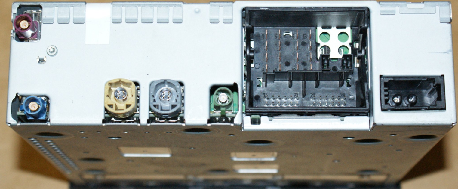
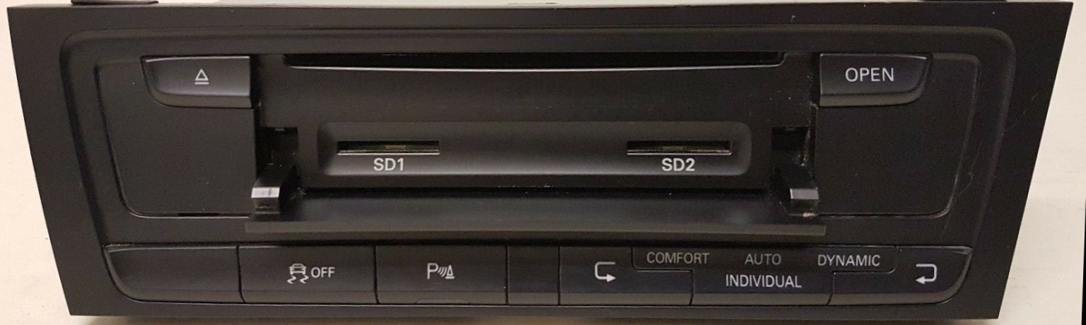
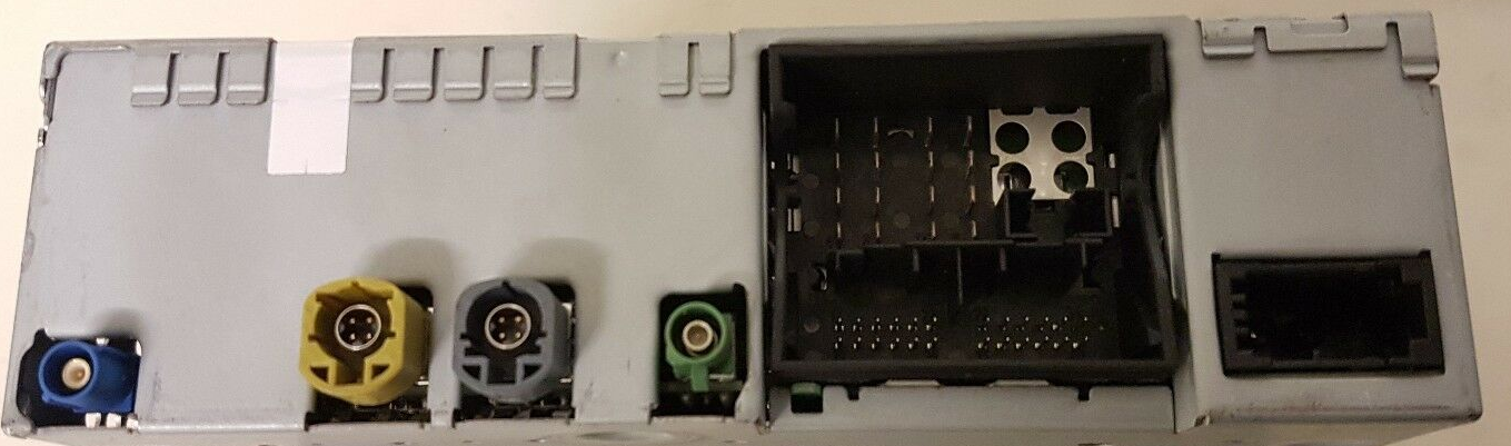
Maximum configuration.
p/n 4L2035670C, 4L2035670E, 4L2035670J, 4L2035670H, 4L2035670G, 4L2035670, 4L2035670A, 4L2035670B, 4L2035670K, 4L2035670L
Top right connector (GSM Antenna Connector) Blue Connetor (GPS), green connector (CVBS TV Tuner input)
Average Configuration.
p/n 8T2035666
Minimal Configuration.
p/n 4L0035646 , 4L0035646X, 4L0035646A, 4L0035646AX, 4L0035646B, 4L0035646BX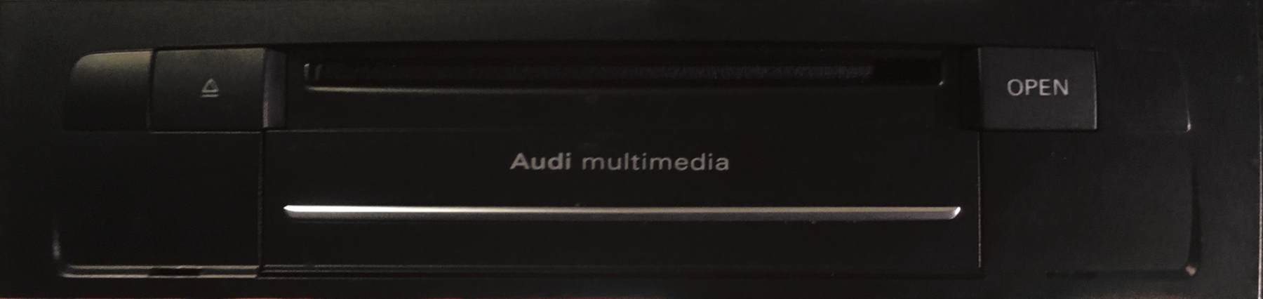
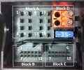
16 pin A connector
| Pin Number |
MMI with minimal equipment | MMI with average equipment | MMI with maximum equipment |
|---|---|---|---|
| 1 | LF mute from preliminary setup for cell phone preparation | N/C | LF mute from preliminary setup for cell phone preparation |
| 2 | Voltage supply to Multimedia Control Head | ||
| 3 | Wake UP to multimedia system control head | ||
| 6 | Reset to multimedia system control head | ||
| 5 | N/C | N/C | Switch-on signal for the Cellular Telephone Amplifier |
| 6 | Reset to the Multimedia System Control Head | ||
| 7 | Ring-break diagnostic cable | ||
| 9 | N/C | N/C | Switch-on signal to Telephone Baseplate |
| 10 | Data from multimedia system control head | ||
| 11 | Data to the multimedia system control head | ||
| 12 | Terminal 31 (GND) | ||
| 13 | N/C | N/C | DIAG signal from Telephone Baseplate |
| 14 | Reset from multimedia system control head | ||
| 15 | Terminal 30 (BAT+) | ||
| 16 | Ground (GND) to multimedia system control head | ||
12 pin B connector (blue)
| Pin Number |
MMI with minimal equipment | MMI with average or maximum equipment |
|---|---|---|
| 2 | Microphone IN (+) for the microphone unit in front roof module (Right) | |
| 3 | Microphone IN (-) for the microphone unit in front roof module (Right) | |
| 5 | CVBS wire (-) from Rear View Camera System Control Module | |
| 8 | Microphone IN (+) for the microphone unit in front roof module | Microphone IN (+) for the microphone unit in front roof module (Left) |
| 9 | Microphone IN (-) for the microphone unit in front roof module | Microphone IN (-) for the microphone unit in front roof module (Left) |
| 11 | CVBS wire (+) from Rear View Camera System Control Module |
12 pin C connector (green)
| Pin Number |
MMI with minimal, average or maximum equipment |
|---|---|
| 1 | LF-In ground |
| 2 | Right LF-In |
| 3 | USB (+5V) |
| 4 | USB (ground) |
| 6 | Detect |
| 7 | Left LF-In |
| 8 | LF-In ground shielding |
| 9 | CVBS cable (+) |
| 10 | CVBS cable (-) |
| 11 | iPod data |
| 12 | iPod data |
4 pin display unit Connector
| Pin Number |
Function |
|---|---|
| 1 | LVDS (-) |
| 2 | LIN |
| 3 | LVDS(+) |
| 4 | Earth |
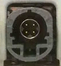
4 pin USB Connector
| Pin Number |
Function |
|---|---|
| 1 | D+ |
| 2 | iPod detected |
| 3 | D- |
| 4 | Earth |
Pins not mentioned are not connected.
This is the same setup as the A & S models 3, 5, 6, 7, 8...
 правильная
 с ошибками