
| Pin Number |
wire color | Pin Name |
Description |
|---|---|---|---|
| 6 | P | Steering switch signal A | Keep pressing SOURCE switch. 0 V Keep pressing MENU UP switch. 0.7 V Keep pressing MENU DOWN switch. 1.3 V Keep pressing Phone switch 2.0 V Except for above. 3.3 V |
| 7 | V | ACC power supply | Ignition - Battery voltage |
| 9 | R | Illumination signal | ON=>12V, OFF=>0V |
| 15 | B | Ground | |
| 16 | L | Steering switch signal B | Keep pressing VOL DOWN switch. 0 V Keep pressing VOL UP switch. 0.7 V Keep pressing switch. 1.3 V Except for above. 3.3 V |
| 19 | Y | Battery power supply | Battery voltage |
| 20 | B | Ground |
| Pin Number |
wire color | Pin Name |
Description |
|---|---|---|---|
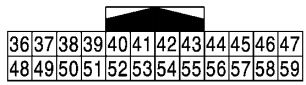
| 36 | O | Signal VCC |
8.8 V out |
| 37 | LG | Signal ground |
|
| 38 | R | Horizontal synchronizing(HP) signal |
|
| 39 | BR | Communication signal (DISP→CON) |
|
| 40 | B | RGB area (YS) signal |
|
| 41 | shield | ||
| 42 | W | RGB synchronizing signal |
|
| 43 | G | RGB signal (R: red) |
|
| 44 | L | RGB signal (G: green) |
|
| 45 | P | RGB signal (B: blue) |
|
| 46 | V | Composite image signal ground |
|
| 47 | SB | Composite image signal |
|
| 48 | Y | Inverter VCC |
8.8V out |
| 49 | BR | Inverter ground |
|
| 50 | G | Vertical synchronizing (VP)signa |
|
| 51 | Y | Communication signal(CONT→DISP) |
|
| 52,57,58 | Shield |

| Pin Number |
wire color | Pin Name |
Description |
|---|---|---|---|
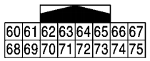
| 61 | G | AUX image signal |
|
| 62 | W | Camera image signal |
|
| 69 | R | AUX image signal ground |
|
| 70,71 | B | shield |

| Pin Number |
wire color | Pin Name |
Description |
|---|---|---|---|
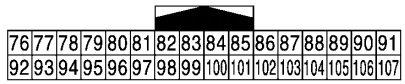
| 76 | Y | AV communication signal (L) |
|
| 77 | G | AV communication signal (H) |
|
| 78 | B | AV communication signal (L) |
|
| 79 | G | AV communication signal (H) |
|
| 80 | P | CAN–L |
|
| 81 | L | CAN–H |
|
| 82 | B | Switch ground |
|
| 86 | shield | ||
| 87 | L | TEL voice signal |
|
| 88 | P | TEL voice ground | |
| 92 | R | Vehicle speed signal (8-pulse) |
|
| 93 | V | Parking brake signal |
|
| 94 | O | Reverse signal |
|
| 95 | G | Ignition signal |
|
| 96 | Y | Disk eject signal |
|
| 102 | B | AUX GND |
|
| 103 | W | AUX sound signal LH |
|
| 104 | R | AUX sound signal RH |

| Pin Number |
wire color | Pin Name |
Description |
|---|---|---|---|
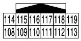
| 108 | V | Sound signal rear RH |
|
| 109 | P | Sound signal front RH |
|
| 110 | W | Amp. ON signal |
|
| 111 | B | shield | |
| 112 | BR | Sound signal rear LH |
|
| 113 | R | Sound signal front LH |
|
| 114 | LG | Sound signal rear RH GND |
|
| 115 | L | Sound signal front RH GND |
|
| 118 | Y | Sound signal rear LH GND |
|
| 119 | G | Sound signal front LH GND |


| Pin Number |
wire color | Pin Name |
Description |
|---|---|---|---|
| 120 | B | Satellite radio sound signal LH |
|
| 121 | G | Satellite radio sound signal RH |
|
| 122 | B | Communication signal(CONT→SAT) |
|
| 124 | W | Satellite radio sound signal LH GND |
|
| 125 | R | Satellite radio sound signal RH GND |
|
| 126,127 | shield | ||
| 128 | SB | Mode change signal |
|
| 129 | W | Request signal(SAT→CONT) |
|
| 130 | R | Communication signal(SAT→CONT) |

| Pin Number |
wire color | Pin Name |
Description |
|---|---|---|---|
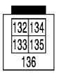
| 132 | G | USB ground |
|
| 133 | R | USB D− signal |
|
| 134 | W | V BUS signal |
|
| 135 | L | USB D+ signal |
|
| 136 | shield |
 правильная
 с ошибками