| Pin Number |
Pin Name |
Description |
| 1 | A1 | CAN B (BUS B) |
| 2 | A2 | BOSE Amp input |
| 3 | A3 | CAN A (BUS B) |
| 4 | A4 | ACC+ |
| 5 | A5 | Power for Electric Antenna. Output from the stereo +12 V (maximum 150 - 300mA) power supply for automatic or electronic antennas. |
| 6 | A6 | N/C |
| 7 | A7 | +12V Battery Power |
| 8 | A8 | Ground (Chassis) |
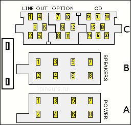
Car audio ISO connector B pinout
Connector B is used only for the speakers. Which wire goes to which speaker can be easily determined with a battery of 1.5 V. Speaker will click and you will see the diaphragm move forward or backward. Speakers must be properly phased (note the + and - half on the speaker), because otherwise you will have weak bass. Wire with a stripe usually goes to + pole of speaker.
| Pin Number |
Pin Name |
Description |
| 1 | B1 | Right Rear + |
| 2 | B2 | Right Rear - |
| 3 | B3 | Right Front + |
| 4 | B4 | Right Front - |
| 5 | B5 | Left Front + |
| 6 | B6 | Left Front - |
| 7 | B7 | Left Rear + |
| 8 | B8 | Left Rear - |
Car audio ISO connector C pinout
Connector C are consist of 3 separate connectors that are tied together. It is not always present, sometimes only a part.
| Pin Number |
Pin Name |
Description |
| 1 | C1 | N/C |
| 2 | C2 | N/C |
| 3 | C3 | N/C |
| 4 | C4 | N/C |
| 5 | C5 | N/C |
| 6 | C6 | +12v switched - maximum 150mA |
| 7 | C7 | N/C |
| 8 | C8 | N/C |
| 9 | C9 | Chassis ground |
| 10 | C10 | Steering wheel control buttons |
| 11 | C11 | Steering wheel control buttons |
| 12 | C12 | Steering wheel control buttons reference |
| 13 | C13 | CDC (CD Changer ) data in (bus) |
| 14 | C14 | CDC data out |
| 15 | C15 | CDC +12v permanent |
| 16 | C16 | CDC +12v switched - maximum 300mA (+A) |
| 17 | C17 | CDC data ground (+U) |
| 18 | C18 | CDC audio frequency ground |
| 19 | C19 | CDC audio frequency left |
| 20 | C20 | CDC audio frequency right |


 правильная
 с ошибками