
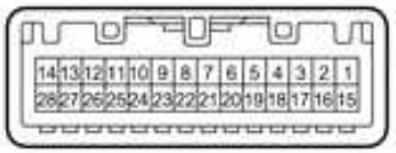
| Pin Number |
Pin Name |
Description | wire color |
|---|---|---|---|
| A1 | FR+ | Sound signal (Front right) | LG |
| A2 | FL+ | Sound signal (Front left) | P |
| A3 | ACC1 | Power source (ACC) | GR |
| A4 | +B1 | Power source (+B) Always 11 to 14 V | SB |
| A5 | FR- | Sound signal (Front right) | L |
| A6 | FL- | Sound signal (Front left) | V |
| A7 | GND1 | Body ground | BR |
| A10 | ILL+ | Illumination signal | G |
| B1 | RR+ | Sound signal (Rear Right) | R |
| B2 | RL+ | Sound signal (Rear left) | B |
| B3 | RR- | Sound signal (Rear right | W |
| B5 | ILL- | Illumination signal | W |
| B6 | RL- | Sound signal (Rear left) | Y |
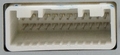
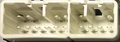
28 pin Head Unit connector
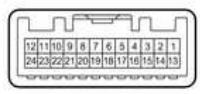
| Pin Number |
Pin Name |
Description | wire color |
|---|---|---|---|
| 1 | IG | Power source ( Ignition switch ON => 11 to 14V) | G |
| 2 | REV | Reverse signal | R |
| 3 | ADIM | Illumination (auto dimmer) signal ( Ignition switch ON, automatic light control sensor covered by hand, and light control switch in auto position => 11 to 14V) |
W |
| 4 | MACC | Microphone power supply (Ignition switch ON => 4 to 6 V) | B |
| 5 | MIN+ | Microphone voice signal | W |
| 6 | SNS2 | Ground | W-B |
| 9 | CANH | CAN communication signal | V |
| 10 | CANL | CAN communication signal | W |
| 11 | AGND | Body ground | |
| 12 | SG | Shield | |
| 13 | VV+ | Video signal | B |
| 14 | VV- | Video signal | W |
| 15 | PKB | Parking brake signal | G |
| 17 | SPD | Vehicle speed signal from combination meter assembly | V |
| 18 | SGND | Shield ground | |
| 19 | MIN- | Microphone voice signal | R |
| 21 | SW1 | Steering pad switch signal No switch pushed 2.97 to 3.56 V Up switch pushed 0.27 to 0.35 V Up switch pushed 0.86 to 1.03 V Volume+ switch pushed 1.51 to 1.79 V Volume- switch pushed 2.22 to 2.66 V |
Y |
| 21 | SW2 | Steering pad switch signal No switch pushed 2.97 to 3.56 V MODE/HOLD switch pushed 0.27 to 0.35 V On hook switch pushed 0.86 to 1.03 V Off hook switch pushed 1.51 to 1.79 V Voice switch pushed 2.22 to 2.66 V |
G |
| 23 | SWG | Steering pad switch signal ground | V |
| 25 | ADPG | External device connection detection signal ( External device not connected => 2.1 to 3 V) | G |
| 26 | VAR+ | Sound signal (Right) external device | B |
| 27 | VA- | Sound signal ground | W |
| 28 | VAL+ | Sound signal (Left) external device |
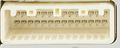
| Pin Number |
Pin Name |
Description | wire color |
|---|---|---|---|
| 3 | CNH1 | Local bus communication signal | B |
| 4 | CNL1 | Local bus communication signal | W |
 правильная
 с ошибками