| Pin Num |
W/C | Pin | Signal |
|---|---|---|---|
| A1 | LG | FR+ | Sounds signal (front right) |
| A2 | P | FL+ | Sounds signal (front left) |
| A3 | GR | ACC | ACC power supply |
| A4 | L | B+ | Battery |
| A5 | L | FR- | Sounds signal (front right) |
| A6 | V | FL- | Sounds signal (front left) |
| A7 | BR | GND | Ground |
| A8 | B | ANT | Power source ofantenna |
| A10 | G | ILL+ | Illumination signal |
| B1 | R | RR+ | Sounds signal (rear right) |
| B2 | B | RL+ | Sounds signal (rear left) |
| V3 | W | RR- | Sounds signal (rear right) |
| B5 | BR | ILL- | Illumination signal |
| B6 | Y | RL- | Sounds signal (rear left) |
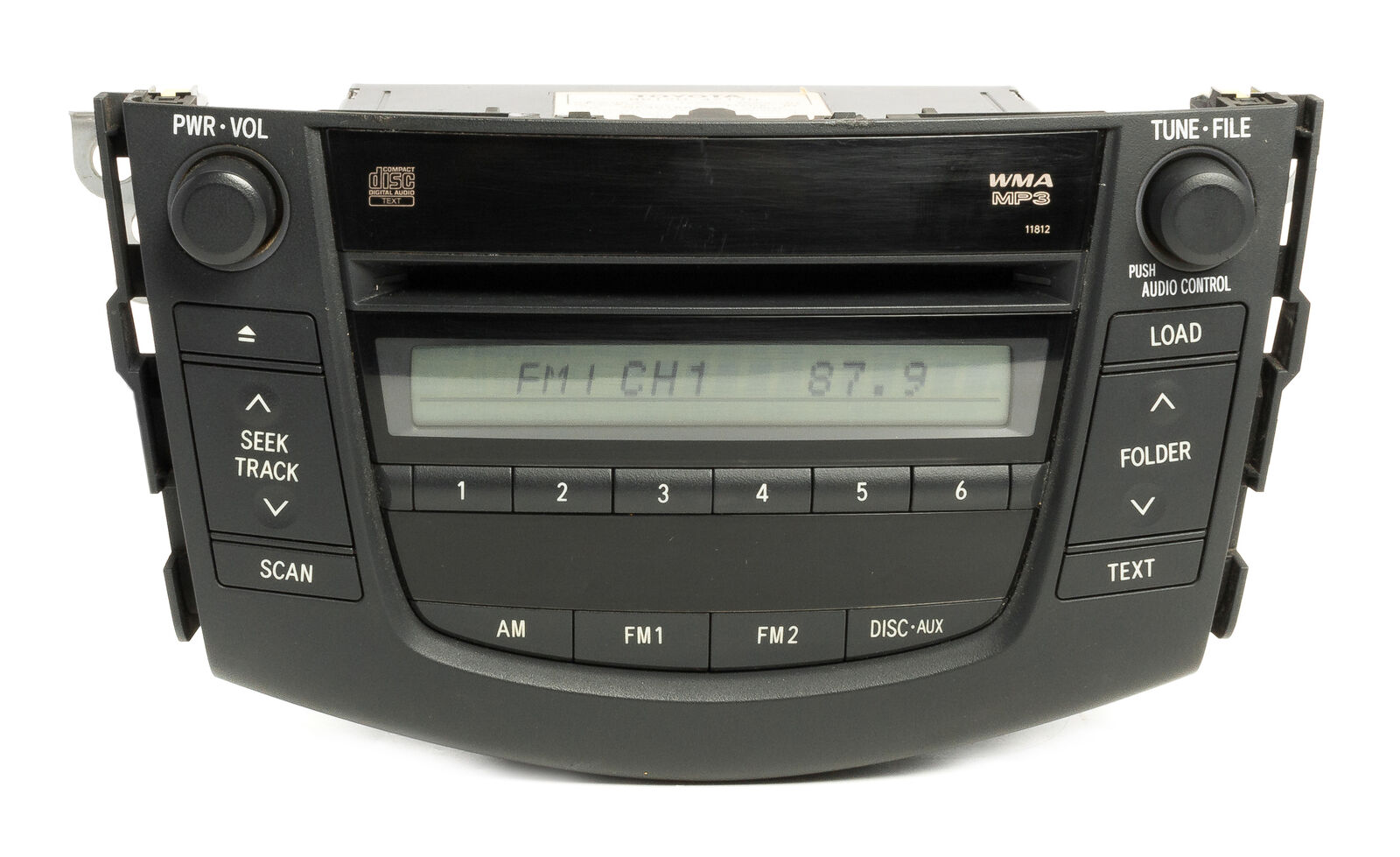
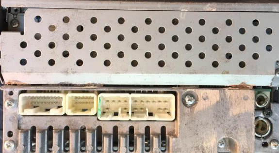
W/C stands for Wire Color. It is RAV4 2011 and very dependent on model and model year.
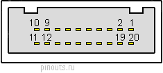
20 pin Connector
| Pin Num |
W/C | Pin | Signal |
|---|---|---|---|
| 6 | B | SWG | Steering pad switch signal ground |
| 7 | W | SW1 | Steering pad switch signal Steering pad switch SEEK+ switch pushed Approx. 0.5 V Steering pad switch SEEK- switch pushed Approx. 0.9 V Steering pad switch VOL+switch pushed Approx. 2.0 V Steering pad switch VOL-switch pushed Approx. 3.4 V Steering pad switch not pushed 4 V or more |
| 8 | R | SW2 | Steering pad switch signal Steering pad switch notpushed 4 V or more Steering pad switch MODEswitch pushed Below 0.5 V |
| 15 | W | ARI | Sound signal (right) |
| 16 | R | ASGN | Ground |
| 17 | B | ALI | Sound signal (left) |
| 18 | AGND | Shielded ground |
|
| 19 | R | AUXI | External input connection detection signal |
W/C stands for Wire Color. It is RAV4 2011 and very dependent on model and model year.


 правильная
 с ошибками