
| Pin Number |
Function |
|---|---|
| 1 | Right Rear Speaker, Positive |
| 2 | Right Front Speaker, Positive |
| 3 | Left Front Speaker, Positive |
| 4 | Left Rear Speaker, Positive |
| 5 | Right Rear Speaker, Negative |
| 6 | Right Front Speaker, Negative |
| 7 | Left Front Speaker, Negative |
| 8 | Left Rear Speaker, Negative |
| 9 | CAN bus high, positive |
| 10 | CAN bus low, negative |
| 11 | n/a |
| 12 | Power Supply, Negative, Terminal 31 |
| 13 | UART TxD |
| 14 | UART RxD |
| 15 | Power supply, positive, terminal 30 |
| 16 | n/a |
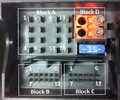
12 pin B connector
| Pin Number |
Function |
|---|---|
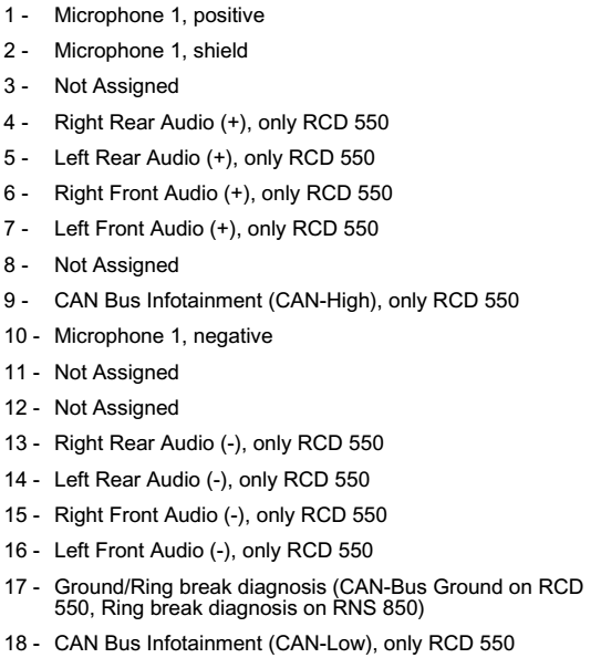
| 5 | Left Telephone Audio Input Signal, Negative |
| 6 | Right Telephone Audio Input Signal, Negative |
| 10 | Telephone Mute (Radio Mute) |
| 11 | Left Telephone Audio Input Signal, Positive |
| 12 | Right Telephone Audio Input Signal, Positive |
12 pin C connector
| Pin Number |
Function |
|---|---|
| 1 | Left Input AUX Signals |
| 2 | AUX Signal Ground |
| 7 | Right Input AUX Signals |
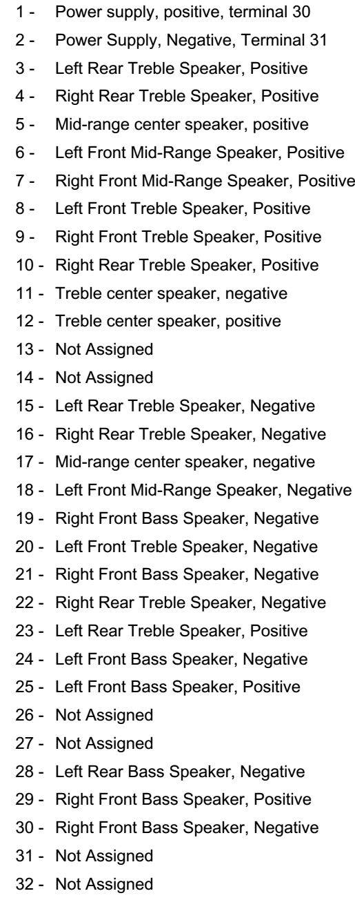
18 pin Connector at the Digital Sound System Control Module
numbering is printed on connector
18 pin Connector at the Digital Sound System Control Module
 правильная
 с ошибками