
The SNES pad works exactly the same as the NES controller, except it has two 4021s inside, and there are fifteen pulses on the CLK line, and sixteen bits of data come out the Data line. As a matter of fact, an SNES pad can be connected to an NES by simply swapping the connector on the end. (Note: Some NES controllers seem to have the RED wire as Data Clock and the Yellow wire as Serial Data)
| Pin | Description | Wire Color |
|---|---|---|
| 1 | +5v | White |
| 2 | Data Clock | Yellow/Red |
| 3 | Data Latch | Orange |
| 4 | Serial Data | Red/Yellow |
| 5 | N/C | - |
| 6 | N/C | - |
| 7 | Ground | Brown |
How to connect Nintendo SNES joystick to PC ?
It is possible to adapt a joystick originally developed for Nintendo SNES to a PC. After connecting joystick to PC parallel port, you must install a driver. Note: the parallel port should be configured as ECP in the BIOS setup of the computer (usually already turned on).
   DB25                   SNES
25 pin D-sub             7 pin
male
2--------------------------2
3--------------------------3
5--->|---+
6--->|---+
7--->|---+-----------------1
8--->|---+
9--->|---+
10-------------------------4
18,19----------------------7

->| means 1N4148 diode
18,19 shorted
The diodes better to be soldered inside the DB25 connector. Joystick with this cable will work only after manual drivers install. DirectPad drivers for Windows 2000 or XP may be downloaded from http://www.emulatronia.com/reportajes/directpad/ntpad.zip.
Additional information
Clock pulse and corresponding button
- B
- Y
- Select
- Start
- North
- South
- West
- East
- A
- X
- L
- R
- [no button, always high]
- [no button, always high]
- [no button, always high]
- [no button, always high]
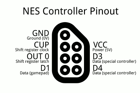
NES joystick controller pinout
 o 4 1 o o 5 2 o o 6 3 o o 7
- +5VDC Supply
- OUT 0
- D1
- GND
- CLK
- Latch
- Data out
The NES starts the show by pulsing the Latch line high, which tells the shift register inside the controller (equivalent to a CMOS 4021) to grab and store the state of all buttons. The state of the first button (A) is immediately visible on the Data Out line.
The NES then sends a series of seven low pulses down the CLK line, which makes the controller shift the stored button state bits (one for each CLK pulse) onto the Data Out line. A low bit on the Data Out line means the button was pressed.
Clock pulse and corresponding button
- B
- Select
- Start
- North
- South
- West
- East
Pins 2 & 3 are extra digital input lines which aren't used by the standard pad. They're used with alternative controllers, including the Zapper light gun, Power Pad, and Arkanoid paddle.
 правильная
 с ошибками