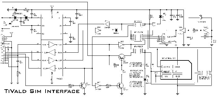
 Click on image to enlarge it.
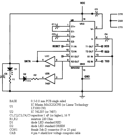
Another scheme (not such complicated)

The adapter electronic gets its power supply from the smartcard reader device VCC line or you can use an external 5 V supply if you wish. The card slots RST line is connected using one of the TTL->RS-232 drivers in the MAX232 to DCD, so that the software and the reader can easily resynchronize in case of a protocol error.
You can test the circuit with a terminal emulator and external +5 V supply by switching of local echo if you still see every typed character immediately on the screen, the interface should be all right.
You can also use this adapter circuit to allow a PC to listen to the data traffic between a reader and a real card. Just connect the real card and the adapter parallel to the reader and dont let the PC software transmit anything.


 правильная
 с ошибками