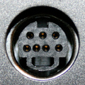
| Pin | Name | Description |
|---|---|---|
| 1 | GND | Ground (Y) |
| 2 | GND | Ground (C) |
| 3 | Y | Intensity (Luminance) |
| 4 | C | Color (Chrominance) |
| 5 | VGND | Composite Ground |
| 6 | - | - |
| 7 | V | Composite Video |
Generally the first four pins on those 7-pin connectors on the same places as the standard four pin S-video connector have practically always the same fuctionality as those pins in S-video connector.
9800 used 7-pin connector, with s-video normal, composite signal on top-center and composite ground on S-video luminance ground.
X1050 and X1950 use 9-pin connector in card and 7, 8 or 9 pin connector on adapters (bottom 2 pins are unused at least on composite and component video adapters) S-video is normal, Composite is same as 9800 but composite ground is also connected to the connector shield.
YPbPr component adapter uses all 4 middle-row pins and connector shield for ground (all connected together in adapter), Y signal is top-left, Pb signal is top-center and Pr signal is top-right.
| Pin | Name | Description |
|---|---|---|
| 1 | GND | Ground (Y) |
| 2 | GND | Ground (C) |
| 3 | Y | Component: to green RCA |
| 4 | Pr/Cr | Component: to red RCA |
| 5 | GND | Ground |
| 6 | GND | Ground |
| 7 | Pb/Cb | Component: to blue RCA |
In X1650 pin 2 must be left open and other middle-row pins and connector shield must be connected to ground. Signal pins are like in table above.


 правильная
 с ошибками