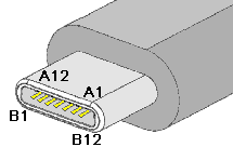
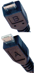
USB Type-C specification defines a small reversible-plug connector for USB devices. Micro-USB 2.0 to USB-C is a USB2.0-only version of USB-C Full-Featured cable.
USB 2.0 micro-B to USB-C cable pinout
| USB-C signal Description | USB-C Signal | Pin | Pin | USB Standard-A signal | USB Description |
|---|---|---|---|---|---|
| Ground | GND | A1,B1, A12,B12 | 5 | GND | Ground |
| Bus Power | VBUS | A4,B4,A9,B9 | 1 | Vbus | USB Vbus |
| Configuration channel. Pin shall be connected to GND through a resistor 5.1 kΩ | CC | A5 | N/C | ||
| optional power supply for active cables schemes | VCONN | B5 | N/C | ||
| USB differential pair, position 1, positive | Dp1 | A6 | 3 | D+ | USB 2.0 differential pair, positive |
| USB differential pair, position 1, negative | Dn1 | A7 | 2 | D- | USB 2.0 differential pair, negative |
| 4 | ID | Micro-USB ID pin. Shall be terminated as defined in the applicable specification for the cable type | |||
| Outer shield | shell | shell | Outer shield |
Contacts B6 and B7 should not be present in the USB Type-C plug. The receptacle side shall support the USB 2.0 differential pair present on Dp1/Dn1 or Dp2/Dn2. The plug orientation determines which pair is active.
USB-C cables that do not have shielded SuperSpeed pairs, sideband use pins, or additional wires for power lines can have increased cable length, up to 4 m. These USB-C cables only support 2.0 speeds and do not support alternate modes.
The USB Type-C Power-Only plug is a depopulated version of the USB Full-Featured Type-C plug or the USB 2.0 Type-C plug. Contacts for configuration channel, Vbus, and GND (i.e., A1, A4, A5, A9, A12, B1, B4, B9, and B12) shall be present, others are optional. Implementation of resistor or CC communication on pin A5 is required.


 правильная
 с ошибками